Raspberry Pi Developer's Guide: Remote Control
無線遙控器常見的有2種, 一種是家電常用的紅外(IR)遙控模式, 另一種是防盜報警設備、門窗遙控、汽車遙控等等常用的無線電(RF)遙控模式。
無線電的使用距離較遠,應用範圍較廣,從遊戲用遙控賽車到汽機車遙控、防盜保全等應用。
無線遙控的原理就是發射機把控制的電信號先編碼, 然後再調製:
- 紅外調製, 或者
- 無線調頻、調幅
IR Remote Control
紅外遙控器的原理
關於遙控器
遙控器其核心元器件就是編碼芯片,將需要實現的操作指令例如選台、快進等事先編碼,設備接收後解碼再控制有關部件執行相應的動作。
顯然,接收電路及 CPU 也是與遙控器的編碼一起配套設計的。
編碼是通過載波輸出的,即所有的脈衝信號均調製在載波上,載波頻率通常為 38K。
載波是電信號去驅動紅外發光二極管,將電信號變成光信號發射出去,這就是紅外光,波長范圍在 840nm 到 960nm 之間。
在接收端,需要反過來通過光電二極管將紅外線光信號轉成電信號,經放大、整形、解調等步驟,最後還原成原來的脈衝編碼信號,完成遙控指令的傳遞,這是一個十分複雜的過程。
紅外線發射管通常的發射角度為 30-45 度之間,角度大距離就短,反之亦然。
遙控器在光軸上的遙控距離可以大於 8.5 米,與光軸成 30 度(水平方向)或 15 度(垂直方向)上大於 6.5 米,在一些具體的應用中會充分考慮應用目標,在距離角度之間需要找到某種平衡。
對於遙控器涉及到如下幾個主要問題:
- 遙控器發出的編碼信號驅動紅外線發射管,必需發出波長範圍在 940nm 左右的的紅外光線 因為紅外線接收器的接收二極管主要對這部分紅外光信號敏感,如果波長范圍不在此列, 顯然無法達到控制之目的。不過,幾乎所有的紅外家電遙控器都遵循這一標準。正因為有這 一物理基礎,多合一遙控器才有可能做成。
- 遙控器發出一串編碼信號只需要持續數十 ms 的時間 大多數是十多 ms 或一百多 ms 重復一次,一串編碼也就包括十位左右到數十位二進制編碼,換言之,每一位二進制編碼的持 續時間或者說位長不過 2ms 左右,頻率只有 500kz 這個量級,要發射更遠的距離必需通過載波,將這些信號調製到數十 khz,用得最多的是 38khz,大多數普通遙控器的載波頻率是所用的陶瓷振盪器的振盪頻率的 1/12,最常用的陶瓷振盪器是 455khz 規格,故最常用的載波也就是 455khz/12=37.9khz,簡稱 38k 載波。 此外還有 480khz(40k)、440khz(37k)、432khz(36k)等規格,也有 200k 左右的載波,用於高速編碼。 紅外線接收器是一體化的組件,為了更有針對性地接收所需要的編碼,就設計成以載波為中心頻率的帶通濾波器,只容許指定載波的信號通過。顯然這是多合一遙控器應該滿足的第二個物理條件。不過,家用電器多用38k,很多紅外線接收器也能很好地接收頻率相近的 40k 或 36k 的遙控編碼。
- 一個設備受控,除了滿足上面提到的兩個基本物理條件外,最重要的變化多種多樣的當然應該是遙控器發出一串二進制編碼信號了 這也是不同的遙控器不能相互通用的主要原因。 由於市場上出現成百上千的編碼方式並存,並沒有一個統一的國際標準,只有各芯片廠商事 實上的標準,這也是模擬並替換各種原廠遙控器最大的難點。隨著技術的不斷發展,很多公 司開發家電設備的遙控子系統時還不採用通用的編碼芯片,而是用通用的單片機隨心所欲地 自編一些編碼,這就使通用遙控的問題更加複雜化了。
- 採用同樣的編碼芯片,也不意味著可以通用,因為還有客戶碼 客戶碼設計的最初本意就是為了不同的設備可以相互區分互不干擾。 最初芯片廠商會從全局考慮給不同的家電廠商安排不同的客戶碼以規範市場,例如錄像機和電視機就用不同的設備碼,給甲廠分配的設備碼 和乙廠分配的設備碼就區分在不同的範圍內。
- 採用同樣的編碼芯片、同樣的客戶碼下,也不能意味著一定可以通用 因為對命令碼的分配與使用上,仍然是沒有固定的模式可以遵循,遙控器編碼芯片簡單的支持數十種命令碼, 多的上千種,但遙控器往往只有數十個鍵,甚至只有幾個鍵,如何從中選取這數十個鍵,這 些鍵如何分配使用,不同的系統設計師都自搞一套,這樣一來事情就更複雜化了。 設計需考慮的問題是如何“同化”不同遙控器發射信號之間的差異。遙控編碼方式涉及很多方 面,首先是數字 0 和 1 的表示(調寬還是調相,脈寬和占空比);其次是幀結構(引導碼和 結束碼,客戶碼和命令碼長度及發送方式);再次是幀間結構(僅發一次還是反復多次,多 幀交替發送,幀間間隔變化);最後是載波頻率,以 38Khz 居多,也有 40Khz 甚至 200khz 等特殊載波。 設計相應電路和軟件時對上述諸多因素加以分析、歸納,將編碼特點用一串二進制位表示出 來形成設備碼,對應於一個具體的遙控器。同一個設備碼下也就是同一個遙控器不同的按鍵 則用命令碼來表示。代碼型遙控器用軟件的方式對這些統一的編碼進行解釋,驅動一個個命 令碼按指定設備碼格式加以“封裝”,形成所需要的遙控信號,達到控製家電的目的。
紅外遙控器原理
一般的紅外遙控系統是由紅外遙控信號發射器、紅外遙控信號接收器和微控制器及其外圍電路等三部分構成的。
- 遙控信號發射器用來產生遙控編碼脈衝,驅動紅外發射管輸出紅外遙控信號
- 遙控接收頭完成對遙控信號的放大、檢波、整形、解調出遙控編碼脈衝
- 遙控編碼脈衝是一組組串行二進制碼,對於一般的紅外遙控系統,此串行碼輸入到微控制器,由其
內部 CPU 完成對遙控指令解碼,並執行相應的遙控功能。在紅外遙控系統中,解碼的核心是 CPU。它接收解調出的串行二進制碼,在內部根據本
系統的遙控信號編碼格式將串行碼對應成遙控器上的按鍵。

DIY萬能遙控器
沒有內置紅外線發射器的iPhone或某些Android手機,則必須另購”音訊紅外配件“,其售價雖然不高,不過以資源回收的:- 耳機線
- 遙控器或滑鼠拆解下來的紅外線LED

- IR LED × 2
- 音頻3.5mm立體插頭 × 1
Photo Modules for PCM Remote Control Systems
TSOP 1738


Raspberry Pis, Remotes & IR Receivers!
Testing the IR Sensor
Connect up the sensor like so:- Pin 1 is the output so we wire this to a visible LED and resistor
- Pin 2 is ground
- Pin 3 is VCC, connect to 5V
 Now grab any remote control (TV, BluRay etc…) and point it at the detector. While pressing some buttons, you should see the LED blink a few times! That's it - your receiver is working. . . . !
 Testing the IR Sensor on the Rasberry Pi
Keyes IR Obstacle Avoidance Module KY-032
Pins:
GND – should be connected to ground
– should be connected to 5V power supply
out – obstacle signal
EN – no use found
"""
read state from obstacle avoidance sensor using callback functions
"""
import RPi.GPIO as GPIO
import time

outPin = 15 # out connected to D15
enPin = 16 # EN connected to D16

GPIO.setwarnings(False)
GPIO.setmode(GPIO.BCM)
GPIO.setup(outPin, GPIO.IN, pull_up_down=GPIO.PUD_DOWN)

def eventObstacleSensor(e):
 print("Obstacle found!")
 print(e)

GPIO.add_event_detect(outPin, GPIO.FALLING, bouncetime = 200, callback = eventObstacleSensor)

while(True):
 time.sleep(0.1)
RF Remote Control
Super Simple Raspberry Pi 433MHz Home Automation
This will specifically show you how to turn any electrical device on or off using your Pi by transmitting commands to a set of 433MHz remote-controlled power sockets. The software side of this system consists of two very simple Python scripts : One for receiving and recording signals, and one for transmitting these signals back to the wireless power sockets. The actual reception/transmission of the signal relies only on the easy-to-use RPi.GPIO library which, at least for me, came pre-installed with Raspbian. This library can also be imported directly into Python. For this project you will need:- A Raspberry Pi. Any model should work, I used a Pi 2 model B starter kit, but perhaps you need the central unit only.
- A 433MHz transmitter/receiver pair. The ones most commonly used in this type of project seem to be these. Buying a pack of five like the one linked ensures that you have a few spares.
- TX Technical: Working voltage: 3V-12V
- Working temperature: -10℃ to +70℃
- Resonance mode: sound wave resonance (SAW)
- Modulation mode: ASK/ OOK
- A set of 433MHz remote-controlled power sockets. I bought these which I'd highly recommend, but there are countless models available. Just make sure they operate on this frequency!
- Remote Control Set 1 + 3 RCS 1000 Comfort
- The comfortable way for switching electrical equipment on/off by a remote control button
- Plug receiver socket into the main socket and the appliance you wish to use into the receiver socket
- Particularly suitable for operating lamps and other electrical items, which are inaccessible
- Extremely useful for people with mobility difficulties
- Switching capacity max
- 1
- 000 W
- Childproof socket
- Works up to a distance of 25 metres
- Frequency 433,92 MHz
- Scope of delivery: 1 x 4 channel sender, 3 x remote receivers sockets, 1 x 12 V battery type A23
- Some circuit-building accessories. I'd recommend using a breadboard and some jumper cables to make the circuit building process as easy as possible.


Step 1: Setting Up the Receiver Unit
Before you can use your Pi to send commands to the remote-controlled sockets, you need to know what specific signals they respond to. Most remote-controlled sockets ship with a handset that can be used to turn specific units on or off. In the case of the ones I bought, the handset has four rows of paired ON/OFF buttons, each of which sends out an ON or OFF signal to a particular socket unit. This brings up a question - how do we know which buttons correspond to which socket? This actually depends on the model you have. One of the main reasons I chose my particular model of socket (linked in the introduction) is that each unit has a small set of switches on the back which can be manually configured to make a particular socket respond to a particular set of ON/OFF buttons on the handset. This also means that you can unplug and move the sockets around the house knowing that a particular unit will always respond to the same ON/OFF signals. Once you have figured out how your sockets interact with the handset, you will need to use your 433MHz receiver unit (pictured above) to 'sniff' the codes being sent out by the handset. Once you have recorded the waveforms of these codes, you can replicate them using Python and send them out using the transmitter unit. The first thing to do here is wire the pins on your receiver to the correct GPIO pins on the Pi. The receiver unit has four pins, but only three of them are needed. I think both of the central pins give the same output, so you only need to connect to one of them (unless you want to stream the received signals to two separate GPIO pins).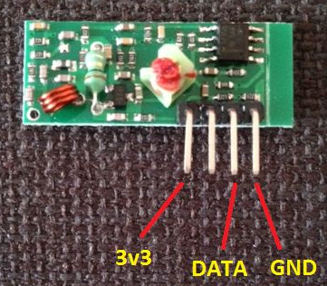
Step 2: Sniffing the Handset Codes
Now that your receiver is wired up to the Pi, you can start the first exciting stage of this project - the sniff. This involves using the attached Python script to record the signal transmitted by the handset when each button is pressed. The script is very simple, and I'd highly recommend you have a look at it before you run it - after all, the point of this project is that you won't just blindly run someone else's code!
from datetime import datetime
import matplotlib.pyplot as pyplot
import RPi.GPIO as GPIO

RECEIVED_SIGNAL = [[], []]  #[[time of reading], [signal reading]]
MAX_DURATION = 5
RECEIVE_PIN = 23

if __name__ == '__main__':
    GPIO.setmode(GPIO.BCM)
    GPIO.setup(RECEIVE_PIN, GPIO.IN)
    cumulative_time = 0
    beginning_time = datetime.now()
    print '**Started recording**'
    while cumulative_time < MAX_DURATION:
        time_delta = datetime.now() - beginning_time
        RECEIVED_SIGNAL[0].append(time_delta)
        RECEIVED_SIGNAL[1].append(GPIO.input(RECEIVE_PIN))
        cumulative_time = time_delta.seconds
    print '**Ended recording**'
    print len(RECEIVED_SIGNAL[0]), 'samples recorded'
    GPIO.cleanup()

    print '**Processing results**'
    for i in range(len(RECEIVED_SIGNAL[0])):
        RECEIVED_SIGNAL[0][i] = RECEIVED_SIGNAL[0][i].seconds + RECEIVED_SIGNAL[0][i].microseconds/1000000.0

    print '**Plotting results**'
    pyplot.plot(RECEIVED_SIGNAL[0], RECEIVED_SIGNAL[1])
    pyplot.axis([0, MAX_DURATION, -1, 2])
    pyplot.show()
from datetime import datetime
import matplotlib.pyplot as pyplot
import RPi.GPIO as GPIO
sudo apt-get install python-matplotlib
Step 3: Transcribing the Resulting Signal

1 = short_on + long_off
0 = long_on + short_off
1111111111111010101011101
- The duration of a 'short' interval, i.e. the beginning of a 1 or the end of a 0.
- The duration of a 'long' interval, i.e. the end of a 1 or the beginning of a 0.
- The duration of an 'extended' interval. I noticed that when I held a button down on the handset, there was an 'extended_off' period between each repeated instance of the signal block. This delay is used for synchronisation and has a fixed duration.
- short_delay = 0.00045
- long_delay = 0.00090 (twice as long as a 'short')
- extended_delay = 0.0096
Step 4: Setting Up the Transmitter Unit
Once you have collected your codes and timing data, you can disconnect your receiver unit as you will no longer need it. You can then wire up the transmitter directly to the relevant Pi GPIO pins as shown in the above image. I've found that the pins on the transmitter units are labelled, which makes the process easier. In this case, it is OK to power the unit using the 5v supply from the Pi as the DATA pin will not be sending signals to the Pi, only receiving them. Also, a 5v power supply will provide more transmission range than using the 3v3 supply. Again, you can connect the DATA pin to any appropriate pin on the Pi. I used pin 23 (the same as for the receiver). Another thing I'd recommend doing is adding an antenna to the small hole on the top right of the transmitter. I used a 17cm long piece of straight wire. Some sources recommend a coiled wire of similar length. I'm not sure which is better, but the straight wire provides enough range for me to turn the sockets on/off from any location in my small flat. It is best to solder the antenna, but I just removed some of the plastic from the wire and wrapped the copper through the hole. Once the transmitter is wired up, that's all the hardware setup done! The only thing left to do now is set your sockets up around the house and have a look at the transmitter program.Step 5: Transmitting Signals Using the Pi
This is where the second Python script comes in. It is designed to be just as simple as the first, if not more so. Again, please download it and look over the code. You will need to edit the script to transmit the correct signals according to the data you recorded in step 3, so now's a good time to have a quick glance at it.
import time
import sys
import RPi.GPIO as GPIO

a_on = '1111111111111010101011101'
a_off = '1111111111111010101010111'
b_on = '1111111111101110101011101'
b_off = '1111111111101110101010111'
c_on = '1111111111101011101011101'
c_off = '1111111111101011101010111'
d_on = '1111111111101010111011101'
d_off = '1111111111101010111010111'
short_delay = 0.00045
long_delay = 0.00090
extended_delay = 0.0096

NUM_ATTEMPTS = 10
TRANSMIT_PIN = 23

def transmit_code(code):
    '''Transmit a chosen code string using the GPIO transmitter'''
    GPIO.setmode(GPIO.BCM)
    GPIO.setup(TRANSMIT_PIN, GPIO.OUT)
    for t in range(NUM_ATTEMPTS):
        for i in code:
            if i == '1':
                GPIO.output(TRANSMIT_PIN, 1)
                time.sleep(short_delay)
                GPIO.output(TRANSMIT_PIN, 0)
                time.sleep(long_delay)
            elif i == '0':
                GPIO.output(TRANSMIT_PIN, 1)
                time.sleep(long_delay)
                GPIO.output(TRANSMIT_PIN, 0)
                time.sleep(short_delay)
            else:
                continue
        GPIO.output(TRANSMIT_PIN, 0)
        time.sleep(extended_delay)
    GPIO.cleanup()

if __name__ == '__main__':
    for argument in sys.argv[1:]:
        exec('transmit_code(' + str(argument) + ')')
import time
import sys
import RPi.GPIO as GPIO
a_on = '1111111111111010101011101'
a_off = '1111111111111010101010111'
b_on = '1111111111101110101011101'
b_off = '1111111111101110101010111'
c_on = '1111111111101011101011101'
c_off = '1111111111101011101010111'
d_on = '1111111111101010111011101'
d_off = '1111111111101010111010111'
short_delay = 0.00045
long_delay = 0.00090
extended_delay = 0.0096
python TransmitRF.py code_1 code_2 ...
python TransmitRF.py a_on b_on c_off
Step 6: A Note on Timing Accuracy
As mentioned, the timing between the transmitted on/off pulses is quite important. The TransmitRF.py script uses python's time.sleep() function to build up the waveforms with the correct pulse intervals, but it should be noted that this function is not entirely accurate. The length for which it causes the script to wait before executing the next operation can depend on the processor load at that given instant. That is another reason why TransmitRF.py sends each code multiple times - just in case the time.sleep() function is not able to properly construct a given instance of the code.
from datetime import datetime
import time

def check_sleep(amount):
    start = datetime.now()
    time.sleep(amount)
    end = datetime.now()
    delta = end - start
    return delta.seconds + delta.microseconds/1000000.0

error = 0
for i in range(100):
    error += abs(check_sleep(0.050) - 0.050)
error /= 100
print error
Step 7: Conclusion
This project has presented a method for controlling any electrical appliance using a Raspberry Pi and a set of 433MHz remote-controlled sockets, with a focus on simplicity and transparency. This is the most exciting and flexible project that I have used my Pi for, and there are limitless applications for it. Here are some things I can now do thanks to my Pi:- Turn on an electric heater next to my bed half an hour before my alarm goes off.
- Turn the heater off an hour after I've gone to sleep.
- Turn my bedside light on when my alarm goes off so that I don't fall back to sleep.
- and many more...
at 05:30
python TransmitRF.py c_on
Post a comment

留言