Raspberry Pi : Controlling Motor
Background Knowledge
H - Bridge

An H bridge is an electronic circuit that enables a voltage to be applied across a load in either direction. These circuits are often used in robotics and other applications to allow DC motors to run forwards or backwards.
The term H bridge is derived from the typical graphical representation of such a circuit.
An H bridge is built with four switches (solid-state or mechanical):
- When the switches S1 and S4 (according to the first figure) are closed (and S2 and S3 are open) a positive voltage will be applied across the motor.
- By opening S1 and S4 switches and closing S2 and S3 switches, this voltage is reversed, allowing reverse operation of the motor.

Stepper Motor
Stepper Motor is a motor controlled by a series of electromagnetic coils. The center shaft has a series of magnets mounted on it, and the coils surrounding the shaft are alternately given current or not, creating magnetic fields which repulse or attract the magnets on the shaft, causing the motor to rotate.
Stepper motors consist of:
- a permanent magnetic rotating shaft, called the rotor
- electromagnets on the stationary portion that surrounds the motor, called the stator.
Unipolar Stepper Motor 28-BYJ48 has five or six wires and four coils (actually two coils divided by center connections on each coil). The center connections of the coils are tied together and used as the power connection. They are called unipolar steppers because power always comes in on this one pole.
Note that if you want to use L293 Instead of ULN2003 , You will need to leave Red wire No connection .
This Motor has a Gear ratio of 64 , and Stride Angle 5.625° so this motor has a 4096 Steps .
  Steps in One Revolution: (360°/5.625°) = 64 Steps
  Total steps = Steps in One Revolution x Gear Ratio = 64 x 64 = 4096 steps

    /*
       BYJ48 Stepper motor code
       Connect :
       IN1 >> D8
       IN2 >> D9
       IN3 >> D10
       IN4 >> D11
       VCC ... 5V Prefer to use external 5V Source
       Gnd
       written By :Mohannad Rawashdeh
      https://www.instructables.com/member/Mohannad+Rawashdeh/
         28/9/2013
      */

    #define IN1  8
    #define IN2  9
    #define IN3  10
    #define IN4  11
    int Steps = 0;
    boolean Direction = true;// gre
    unsigned long last_time;
    unsigned long currentMillis ;
    int steps_left=4095;
    long time;
    void setup()
    {
    Serial.begin(115200);
    pinMode(IN1, OUTPUT);
    pinMode(IN2, OUTPUT);
    pinMode(IN3, OUTPUT);
    pinMode(IN4, OUTPUT);
    // delay(1000);

    }
    void loop()
    {
      while(steps_left>0){
      currentMillis = micros();
      if(currentMillis-last_time>=1000){
      stepper(1);
      time=time+micros()-last_time;
      last_time=micros();
      steps_left--;
      }
      }
       Serial.println(time);
      Serial.println("Wait...!");
      delay(2000);
      Direction=!Direction;
      steps_left=4095;
    }


void stepper(int xw){
  for (int x=0;<xw;x++){
switch(Steps){
   case 0:
     digitalWrite(IN1, LOW);
     digitalWrite(IN2, LOW);
     digitalWrite(IN3, LOW);
     digitalWrite(IN4, HIGH);
   break;
   case 1:
     digitalWrite(IN1, LOW);
     digitalWrite(IN2, LOW);
     digitalWrite(IN3, HIGH);
     digitalWrite(IN4, HIGH);
   break;
   case 2:
     digitalWrite(IN1, LOW);
     digitalWrite(IN2, LOW);
     digitalWrite(IN3, HIGH);
     digitalWrite(IN4, LOW);
   break;
   case 3:
     digitalWrite(IN1, LOW);
     digitalWrite(IN2, HIGH);
     digitalWrite(IN3, HIGH);
     digitalWrite(IN4, LOW);
   break;
   case 4:
     digitalWrite(IN1, LOW);
     digitalWrite(IN2, HIGH);
     digitalWrite(IN3, LOW);
     digitalWrite(IN4, LOW);
   break;
   case 5:
     digitalWrite(IN1, HIGH);
     digitalWrite(IN2, HIGH);
     digitalWrite(IN3, LOW);
     digitalWrite(IN4, LOW);
   break;
     case 6:
     digitalWrite(IN1, HIGH);
     digitalWrite(IN2, LOW);
     digitalWrite(IN3, LOW);
     digitalWrite(IN4, LOW);
   break;
   case 7:
     digitalWrite(IN1, HIGH);
     digitalWrite(IN2, LOW);
     digitalWrite(IN3, LOW);
     digitalWrite(IN4, HIGH);
   break;
   default:
     digitalWrite(IN1, LOW);
     digitalWrite(IN2, LOW);
     digitalWrite(IN3, LOW);
     digitalWrite(IN4, LOW);
   break;
}
SetDirection();
}
}
void SetDirection(){
if(Direction==1){ Steps++;}
if(Direction==0){ Steps--; }
if(Steps >h; 7){Steps=0;}
if(Steps < 0){Steps=7; }
}
The following illustrates one complete rotation of a stepper motor.

In the above example, we used a motor with a resolution of 90 degrees.
You may double the resolution of some motors by a process known as "half-stepping". Instead of switching the next electromagnet in the rotation on one at a time, with half stepping you turn on both electromagnets, causing an equal attraction between, thereby doubling the resolution. This process can then be repeated for the entire rotation.

The real-world motors employ a series of mini-poles on the stator and rotor to increase resolution.
An example of a multipole motor can be seen:

the north pole of the rotor's permanent magnet is aligned with the south pole of the stator's electromagnet. Note that multiple positions are aligned at once. In position 2, the upper electromagnet is deactivated and the next one to its immediate left is activated, causing the rotor to rotate a precise amount of degrees. In this example, after eight steps the sequence repeats.


The number of steps per revolution ranges from 4 to 400. Commonly available step counts are 24, 48 and 200.
Resolution is often expressed as degrees per step. A 1.8° motor is the same as a 200 step/revolution motor.
Another way to achieve high positioning resolution is with gearing.
A 32:1 gear-train applied to the output of an 8-steps/revolution motor will result in a 512 step motor.

Unipolar drivers, always energize the phases in the same way. One lead, the "common" lead, will always be negative. The other lead will always be positive. Unipolar drivers can be implemented with simple transistor circuitry. The disadvantage is that there is less available torque because only half of the coils can be energized at a time.
Bipolar drivers use H-bridge circuitry to actually reverse the current flow through the phases. By energizing the phases with alternating the polarity, all the coils can be put to work turning the motor.
A two phase bipolar motor has 2 groups of coils. A 4 phase unipolar motor has 4. A 2-phase bipolar motor will have 4 wires - 2 for each phase. Some motors come with flexible wiring that allows you to run the motor as either bipolar or unipolar.
5-Wire Motor

This style is common in smaller unipolar motors. All of the common coil wires are tied together internally abd brought out as a 5th wire. This motor can only be driven as a unipolar motor.
以三相步進為例,

- 定子上的3個齒(A,B,C)分別有一個激磁線組
- 轉子上4個齒(1,2,3,4)
- 定子上齒的幾何軸線分別依序與轉子上齒的幾何軸線向右錯開0, 60 , 120度. A與齒1對齊, B與齒差60度, C與齒3差120度.( A'就是A, 齒5就是齒1 )
- A通電, B和C不通電 因為齒1與A對齊,所以轉子不動.
- B通電, A和C不通電 齒2為了要與B對齊,轉子會向右移動60度.C與齒3差60度.A'與齒4差120度.
- C通電, A和B不通電 齒3為了要與C對齊,轉子會向右移動60度.A'與齒4差60度.
- A'通電, B和C不通電 齒4為了要與A'對齊,轉子會向右移動60度.
對A、B、C、D 四相繞組輪流供電,則轉子會沿着 A、B、C、D 方向轉動。
由此可知,轉子的轉動速度是與通電的頻率與次數相關, 方向由通電的順序控制.
若通電順序改變為A-AB-B-BC-C-CA-A, 每一步距就變為30度.
28BYJ-48 Stepper Motor
28BYJ-48是4相永磁式減速步進馬達,其外觀如圖3-2.2所示:
28——步進電機的有效最大外徑是28毫米
B ——表示是步進馬達
Y ——表示是永磁式
J ——表示是減速型
48——表示四相八拍
28BYJ-48的內部結構示意圖
先看裡圈,它上面有6個齒,分別標注為0-5,這個叫做轉子,顧名思義,它是要轉動的,轉子的每個齒上都帶有永久的磁性,是一塊永磁體,這就是“永磁式”的概念;再看外圈,這個就是定子,它是保持不動的,實際上它是跟電機的外殼固定在一起的,它上面有8個齒,而每個齒上都纏上了一個線圈繞組,正對著的2個齒上的繞組又是串聯在一起的,也就是說正對著的2個繞組總是會同時導通或關斷的,如此就形成了4相,在圖中分別標注為A-B-C-D,這就是“4相”的概念。
28BYJ-48裡面有內建減速齒輪,所以你要把步進角再除以減速比才是實際step。
28BYJ-48的步進角是5.625/64,馬達本體確實是64 step就轉一圈,但是減速比
是1/64,所以你要64/(1/64) or 64*64 => 4096 step,這樣才會真的轉一圈。
規格5.265/64,是用4 Phase/8 Step來算的,所以如果你用4 Phase/4 Step驅動,
則是11.25/32,加上減速比1/64則為 32/(1/64) or 32*64 => 2048 step一圈。
另外驅動方式是這樣看的,原始spec給的是CCW(逆時針)驅動順序:
4 Phase/8 Step
-------------------------------------
Step | 1 | 2 | 3 | 4 | 5 | 6 | 7 | 8 |
-------------------------------------
紅 | 固定 +5V |
-------------------------------------
橙 | 1 | 1 | 0 | 0 | 0 | 0 | 0 | 1 |
-------------------------------------
黃 | 0 | 1 | 1 | 1 | 0 | 0 | 0 | 0 |
-------------------------------------
粉 | 0 | 0 | 0 | 1 | 1 | 1 | 0 | 0 |
-------------------------------------
藍 | 0 | 0 | 0 | 0 | 0 | 1 | 1 | 1 |
-------------------------------------
先假設你有一個IO Port,其中4 bit,順序由高到低接藍粉黃橙。
照spec逆時針轉的話,則要準備這樣的訊號pattern:
{0x1, 0x3, 0x2, 0x6, 0x4, 0xC, 0x8, 0x9}
正轉就顛倒過來:
{0x9, 0x8, 0xC, 0x4, 0x6, 0x2, 0x3, 0x1}
如果你要用4 Phase/4 Step的方式驅動,則只要看驅動表的step 2,4,6,8
逆轉pattern:
{0x3, 0x6, 0xC, 0x9}
正轉:
{0x9, 0xC, 0x6, 0x3}
我是用單晶片直接操作IO來舉例,arduino上要怎麼對應我就不清楚了。
要注意的是減速齒輪因為他的比例不是完美1/64,實際上大概是1/63.x,所以你連續
轉個幾圈,就會發現有點飄了,便宜的小馬達就這樣,算是不錯了。
28BYJ-48 步進電機有多種减速比:1:64、1:32、1:16, one example:
- 電壓: 5V
- 相數: 4
- 步距腳: 5.625/16
- 減速比: 1:16

- A: orange line
- B: yellow line
- C: pink line
- D: blue line
四相步進電機藉由變動通電時的脈波次數可以是單四拍,雙四拍及八拍等工作方式.

測試:
- 接線
- 步進電機 紅線接+5V,橘黃粉藍分別接驅動版的OUT1,OUT2,OUT3及OUT4.(外接電源要與主機板共接地)
- 驅動版 驅動電壓(外部電源)及邏輯輸入均接5V. 控制步進馬達的輸入(IN1,IN2,IN3,IN4)接主機板的GPIO. 控制步進馬達的PWM脈波(ENA,ENB)接接主機板的GPIO.
| 正轉 | ||||
| IN1 | 0 | 1 | 1 | 1 |
| IN2 | 1 | 0 | 1 | 1 |
| IN3 | 1 | 1 | 0 | 1 |
| IN4 | 1 | 1 | 1 | 0 |
| 0x7 | 0xb | 0xd | 0xe | |
unsigned char forward[4] = {0x07,0x0b,0x0d,0x0e};

void clockwise()
{
  for(int i = 0; i <4 counter-clockwise="" delaymicroseconds="" for="" i="" int="" motorspeed="" setoutput="" void="">= 0; i--)
  {
    setOutput(i);
    delayMicroseconds(motorSpeed);
  }
}

void setOutput(int out)
{
  Write(motorPin1, forward[out] & 1));
  Write(motorPin2, forward[out] & 2));
  Write(motorPin3, forward[out] & 4));
  Write(motorPin4, forward[out] & 8));
}
References
L298N 馬達驅動板( 2 直流 / 1 步進)
這塊 L298N 馬達驅動板可驅動 2 個直流馬達與 1 個步進馬達。
- 步進馬達 (stepper motor) 步進馬達就是一步一步前進的馬達,步進馬達是脈衝馬達的一種,將直流電源透過數位IC處理後,變成脈衝電流以控制馬達。而且馬達旋轉一圈分成數等分(數步),可使角度的控制更為精密。 步進馬達的步進角,亦即步進馬達之解析度(1脈波的轉動量),視步進馬達的規格而定,例如:步進馬達步進角=15° 。亦即每接受一個脈波訊號,步進馬達轉動15°,若輸入24個脈波訊號則可旋轉一圈。因此只要控制輸入脈波的數目,即可決定馬達轉動的角度。
- 直流馬達(DC Motor) 在控速方面比較簡單,只須控制電壓大小即可控制轉速,但此類馬達不宜在高溫、易燃等環境下操作,而且由於馬達中需要以碳刷作為電流變換器(Commutator)的部件(有刷馬達),所以需要定期清理炭刷磨擦所產生的污物。無碳刷之馬達稱為無刷馬達,相對於有刷,無刷馬達因為少了碳刷與軸的摩擦因此較省電也比較安靜。製作難度較高、價格也較高。
內置降壓晶片 78M05,可直接使用外部電源作為驅動板內部的邏輯電源,或是各別使用皆可。
驅動板可控制兩顆直流馬達,經由前方 ENA、IN1、IN2、IN3、IN4和 ENB 輸入接腳,可分別馬達正轉、反轉和停止動作,若配合 PWM 脈衝輸入EN端更可進而控制馬達轉動的速度。
PWM 脈衝輸入可選用賣場的 LED 驅動晶片來做,可降低控制器的負載,且一經設定就會維持固定的 PWM 脈衝訊號,很實用!
Arduino 可選用:LPD8806,LPD1109,LPD6803,WS2811
Raspberry Pi 可選用:LPD6803,LPD886,LPD1109
驅動板可驅動兩相與四相的步進馬達,經由前方的 IN1、IN2、IN3 和 IN4 ( ENA 和 ENB 維持短路狀態 ),可做一相、兩相和一二相激磁正反轉控制。
L298N 驅動板功能參數規格
- 馬達驅動晶片: L298N
- 雙 H 橋式直流 ( 步進 ) 馬達驅動晶片,最大馬達驅動電壓 DC 50V,但請勿超過最大工作功率。
- 降壓晶片:78M05 使用時,將外部輸入電源 ( 電路圖中的 Vcc ) 降壓為 DC 5V 給電路板用,電壓限制範圍在 DC 7V ~ DC 35V
- ENA、ENB、IN1 ~ IN4 邏輯控制信號輸入電壓、消耗電流範圍:
- Low :-0.3V ≤ Vin ≤ 1.5V ( 控制信號無效 )
- HIGH: 2.3V ≤ Vin ≤ Vcc ( 控制信號有效 ) Vcc 為邏輯輸入電壓,電壓範圍:DC 4.5V ~ DC 7V (可使用板上降壓 DC 5V 電)
- 邏輯工作電流範圍:0 ~ 36 mA
- 最大工作功率:25W @ T = 75°
- 儲存溫度:-25°C ~ +130°C
- 驅動板尺寸:43 *43 * 27 mm³ (高度計算只包含散熱片與電路板厚度)


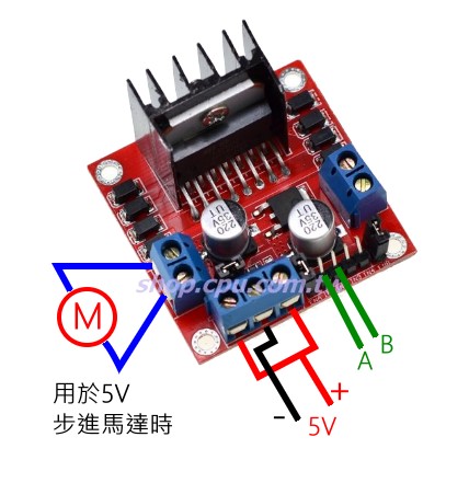
電路圖中的 BAT1 就是照片中綠色轉接頭連接的地方,依照實際馬達驅動電壓輸入就可以了 ( 此處使用的電壓必須大於 5V)

小於 5V 時必須使用兩組電源輸入

商品說明
L298N是ST公司生產的一種高電壓、大電流電機驅動晶片。該晶片採用15腳封裝。主要特點是:工作電壓高,最高工作電壓可達46V;輸出電流大,瞬間峰值電流可達3A,持續工作電流為2A;額定功率25W。內含兩個H橋的高電壓大電流全橋式驅動器,可以用來驅動直流馬達和步進馬達、繼電器線圈等感性負載;採用標準邏輯電平信號控制;具有兩個使能控制端,在不受輸入信號影響的情況下允許或禁止器件工作有一個邏輯電源輸入端,使內部邏輯電路部分在低電壓下工作;可以外接檢測電阻,將變化量反饋給控制電路。使用L298N晶片驅動馬達,該晶片可以驅動一台兩相步進馬達或四相步進馬達,也可以驅動兩台直流馬達
◎ L298N作為主驅動晶片,具有驅動能力強,發熱量低,抗干擾能力強的特點
◎ 內置的78M05通過驅動電源 部分取電工作,但是為了避免穩壓芯片損壞,當使用大於12V驅動電壓的時候,請使用外置的5V邏輯供電
◎ 使用大容量濾波電容,續流保護二極管,可以提高可靠性
注意事項:
1.當你的驅動電壓(上圖標識為12V輸入,實際可以接受的輸入範圍是7-12V)為7V-12V的時候,可以使能板載的5V邏輯供電,當使用板載5V供電之後,介面中的+5V供電不要輸入電壓,但是可以引出5V電壓供外部使用。(這種即為常規應用!)
2.當驅動電壓高於12V,小於等於24V(晶片手冊中提出可以支援到35V,但是按照經驗一般298保守應用最大電壓支援到24V已經很了不起!)時,比如要驅動額定電壓為18V的馬達。首先必須拔除板載5V輸出使能的跳線帽。然後在5V輸出埠外部接入5V電壓對L298N內部邏輯電路供電。(這種是高壓驅動的非常規應用!)
★ 應用實例
1.驅動步進馬達
由於本模組是2路的H橋驅動,所以可以同時驅動兩個馬達,使能ENA ENB之後,可以分別從IN1 IN2輸入PWM信號驅動馬達1的轉速和方向,可以分別從IN3 IN4輸入PWM信號驅動馬達2的轉速和方向


L298注意的事項。雙電源輸入:一個是L298本身使用的電源,一個是馬達電機要使用的電源。
2:驅動直流馬達
由於本模組是2路的H橋驅動,所以可以同時驅動兩個馬達使能ENA ENB之後,可以分別從IN1 IN2輸入PWM信號驅動馬達1的轉速和方向,可以分別從IN3 IN4輸入PWM信號驅動馬達2的轉速和方向信號如圖所示


Control DC and Stepper Motors With L298N Dual Motor Controller Modules
We found a neat motor control module based on the L298N H-bridge IC that can allows you to control the speed and direction of two DC motors, or control one bipolar stepper motor with ease.
This motor controller from Tronixlabs Austalia is based on the L298N heavy-duty dual H-bridge controller, which can be used to drive two DC motors at up to 2A each, with a voltage between 5 and 35V DC - or one stepper motor with ease. The controller has fast short-circuit protection diiodes, and a nice heatsink to keep the L298N happy.
There is also an onboard 5V regulator - so if you're using between 7 and 12V DC to driver the motors, the module can also supply your Arduino (etc) with 5V DC. If you are using more than 12V DC, please remove the 12V jumper (see below).

Module pinouts - match the numbers against the image:
- DC motor 1 "+" or stepper motor A+
- DC motor 1 "-" or stepper motor A-
- 12V jumper - remove this if using a supply voltage greater than 12V DC. This enables power to the onboard 5V regulator
- Connect your motor supply voltage here, maximum of 35V DC. Remove 12V jumper if >12V DC
- GND
- 5V output if 12V jumper in place, ideal for powering your Arduino (etc)
- DC motor 1 enable jumper. Leave this in place when using a stepper motor. Connect to PWM output for DC motor speed control.
- IN1
- IN2
- IN3
- IN4
- DC motor 2 enable jumper. Leave this in place when using a stepper motor. Connect to PWM output for DC motor speed control.
- DC motor 2 "+" or stepper motor B+
- DC motor 2 "-" or stepper motor B-
- logic voltage - 5V
- motor drive voltage - 5~35V DC
- maximum power 25W
Controlling DC Motors
To control one or two DC motors is quite easy with the L298N H-bridge module. First connect each motor to the A and B connections on the L298N module.If you’re using two motors for a robot (etc) ensure that the polarity of the motors is the same on both inputs. Otherwise you may need to swap them over when you set both motors to forward and one goes backwards!
Next, connect your power supply – the positive to pin 4 on the module and negative/GND to pin 5. If you supply is up to 12V you can leave in the 12V jumper (point 3 in the image above) and 5V will be available from pin 6 on the module.
This can be fed to your Arduino’s 5V pin to power it from the motors’ power supply. Don’t forget to connect Arduino GND to pin 5 on the module as well to complete the circuit. Now you will need six digital output pins on your Arduino, two of which need to be PWM (pulse-width modulation) pins.
PWM pins are denoted by the tilde (“~”) next to the pin number, for example in the image of the Arduino Uno's digital pins.
Finally, connect the Arduino digital output pins to the driver module. In our example we have two DC motors, so digital pins D9, D8, D7 and D6 will be connected to pins IN1, IN2, IN3 and IN4 respectively. Then connect D10 to module pin 7 (remove the jumper first) and D5 to module pin 12 (again, remove the jumper).
The motor direction is controlled by sending a HIGH or LOW signal to the drive for each motor (or channel). For example for motor one, a HIGH to IN1 and a LOW to IN2 will cause it to turn in one direction, and a LOW and HIGH will cause it to turn in the other direction.
However the motors will not turn until a HIGH is set to the enable pin (7 for motor one, 12 for motor two). And they can be turned off with a LOW to the same pin(s). However if you need to control the speed of the motors, the PWM signal from the digital pin connected to the enable pin can take care of it.
This is what we’ve done with the DC motor demonstration sketch. Two DC motors and an Arduino Uno are connected as described above, along with an external power supply. Then enter and upload the following sketch:
// connect motor controller pins to Arduino digital pins
// motor one
int enA = 10;
int in1 = 9;
int in2 = 8;
// motor two
int enB = 5;
int in3 = 7;
int in4 = 6;
void setup()
{
  // set all the motor control pins to outputs
  pinMode(enA, OUTPUT);
  pinMode(enB, OUTPUT);
  pinMode(in1, OUTPUT);
  pinMode(in2, OUTPUT);
  pinMode(in3, OUTPUT);
  pinMode(in4, OUTPUT);
}
void demoOne()
{
  // this function will run the motors in both directions at a fixed speed
  // turn on motor A
  digitalWrite(in1, HIGH);
  digitalWrite(in2, LOW);
  // set speed to 200 out of possible range 0~255
  analogWrite(enA, 200);
  // turn on motor B
  digitalWrite(in3, HIGH);
  digitalWrite(in4, LOW);
  // set speed to 200 out of possible range 0~255
  analogWrite(enB, 200);
  delay(2000);
  // now change motor directions
  digitalWrite(in1, LOW);
  digitalWrite(in2, HIGH);
  digitalWrite(in3, LOW);
  digitalWrite(in4, HIGH);
  delay(2000);
  // now turn off motors
  digitalWrite(in1, LOW);
  digitalWrite(in2, LOW);
  digitalWrite(in3, LOW);
  digitalWrite(in4, LOW);
}
void demoTwo()
{
  // this function will run the motors across the range of possible speeds
  // note that maximum speed is determined by the motor itself and the operating voltage
  // the PWM values sent by analogWrite() are fractions of the maximum speed possible
  // by your hardware
  // turn on motors
  digitalWrite(in1, LOW);
  digitalWrite(in2, HIGH);
  digitalWrite(in3, LOW);
  digitalWrite(in4, HIGH);
  // accelerate from zero to maximum speed
  for (int i = 0; i < 256; i++)
  {
    analogWrite(enA, i);
    analogWrite(enB, i);
    delay(20);
  }
  // decelerate from maximum speed to zero
  for (int i = 255; i >= 0; --i)
  {
    analogWrite(enA, i);
    analogWrite(enB, i);
    delay(20);
  }
  // now turn off motors
  digitalWrite(in1, LOW);
  digitalWrite(in2, LOW);
  digitalWrite(in3, LOW);
  digitalWrite(in4, LOW);
}
void loop()
{
  demoOne();
  delay(1000);
  demoTwo();
  delay(1000);
}
Then after a moment the motors operate in the reverse direction (see how we changed the HIGHs and LOWs in thedigitalWrite() functions?). To get an idea of the range of speed possible of your hardware, we run through the entire PWM range in the function demoTwo() which turns the motors on and them runs through PWM values zero to 255 and back to zero with the two for loops.
Finally this is demonstrated in the video on this page – using our well-worn tank chassis with two DC motors.
Controlling a Stepper Motor

It has 200 steps per revolution, and can operate at at 60 RPM. If you don’t already have the step and speed value for your motor, find out now and you will need it for the sketch.
The key to successful stepper motor control is identifying the wires – that is which one is which. You will need to determine the A+, A-, B+ and B- wires. With our example motor these are red, green, yellow and blue. Now let’s get the wiring done.
Connect the A+, A-, B+ and B- wires from the stepper motor to the module connections 1, 2, 13 and 14 respectively. Place the jumpers included with the L298N module over the pairs at module points 7 and 12. Then connect the power supply as required to points 4 (positive) and 5 (negative/GND).
Once again if your stepper motor’s power supply is less than 12V, fit the jumper to the module at point 3 which gives you a neat 5V power supply for your Arduino. Next, connect L298N module pins IN1, IN2, IN3 and IN4 to Arduino digital pins D8, D9, D10 and D11 respectively.
Finally, connect Arduino GND to point 5 on the module, and Arduino 5V to point 6 if sourcing 5V from the module. Controlling the stepper motor from your sketches is very simple, thanks to the Stepper Arduino library included with the Arduino IDE as standard.
To demonstrate your motor, simply load the stepper_oneRevolution sketch that is included with the Stepper library. To find this, click the File > Examples > Stepper menu in the Arduino IDE.
Finally, check the value for
const int stepsPerRevolution = 200;
in the sketch and change the 200 to the number of steps per revolution for your stepper motor, and also the speed which is preset to 60 RPM in the following line:
myStepper.setSpeed(60);
Now you can save and upload the sketch, which will send your stepper motor around one revolution, then back again. This is achieved with the function
  myStepper.step(stepsPerRevolution); // for clockwise
  myStepper.step(-stepsPerRevolution); // for anti-clockwise
Finally, a quick demonstration of our test hardware is shown in the video on this step.
Raspberry PI L298N Dual H Bridge DC Motor

Pins:
- Out 1: Motor A lead out
- Out 2: Motor A lead out
- Out 3: Motor B lead out
- Out 4: Mo (Can actually be from 5v-35v, just marked as 12v)
- GND: Ground
- 5v: 5v input (unnecessary if your power source is 7v-35v, if the power source is 7v-35v then it can act as a 5v out)
- EnA: Enables PWM signal for Motor A
- In1: Enable Motor A
- In2: Enable Motor A
- In3: Enable Motor B
- In4: Enable Motor B
- EnB: Enables PWM signal for Motor B
What is an "H-Bridge" and how does a DC motor change direction?
An H-Bridge is a circuit that can drive a current in either polarity and be controlled by *Pulse Width Modulation (PWM).When you hook a dc motor up to {+} wire on one lead and {-} wire on the other lead, the motor turns a certain direction. When you switch the wires to other leads, the motor turns the other direction. But how do we "electronically" switch the electric polarity using circuits. ANSWER: H-Bridge.
The circuits for H-Bridges are non-trivial for the beginner. The L298N module is a simple ready to rock and roll "dual" H-bridge circuit board. That means you have the ability to control TWO motors in either direction.
You need to get the module board for this.
Double H bridge drive Chip: L298N
- Logical voltage: 5V
- Drive voltage: 5V-35V
- Logical current: 0mA-36mA
- Drive current: 2A(MAX single bridge)
- Storage temperature: -20 to +135
- Max power: 25W
- Operating voltage: 3V~12VDC (recommended operating voltage of about 6 to 8V)
- Maximum torque: 800gf cm min (3V)
- No-load speed: 1:48 (3V time)
- The load current: 70mA (250mA MAX) (3V)
Step 1: Extra DC Power Supply Dedicated for Motor
The motor needs a DC power supply in the Voltage range of the motor. I used a left over 5V old power supply.
Make sure the power supply has enough amperage or power to make the motor turn what ever you're looking to drive.(Complete Guide to Using the Correct Charger or Power Adapter)
You can use the power from batteries to run your motors too.
NEVER USE RASPBERRY PI built in power to DRIVE motors.
If you're building something for real rather than just a quick learning tutorial like this one. Make sure you match you power drive to the motor requirements. Every motor needs different drive voltages. If you have less voltage than the motor needs then the motor will be under powered and may not turn what you want or might burn your power supply out, or worst start melting stuff. If your power supply is too high like for example you put 9 or 12 volts into a 6 volt motor, then the motor will turn really fast and hard. You see people hack their kids toy race cars with bigger batteries, the cars go fast and have a ton more power than the default design. These tricks always come at a costs for safety, reliability, and component breaking (melting, fires etc).
Step 2: Connector Wires for Driving the Direction on the Motor.
The "GPIO" pins on the Raspberry PI will be used to "trigger" the l298n direction.
There are TWO pins per motor. One pin drives the power, {+} to one lead when the pin is activated.
Step 3: BREAD BOARD for Simplifying Wire Connections.
- hook your Raspberry USB micro charger up to your standard PI input.
- hook your 2nd power supply for your DC motor up to the + - on the bread board.
Step 4: Code Snippet Python Sample Make Motor Turn One Way Then Other
Code snippets for python.
This page assume you have enough knowledge of python to know it's a programming language that's human readable and typed into a text file. Some experience with copy and paste will be required. Read the error messages and happy hacking your python motor codes.
There are virtual "GPIO" names for certain pins that are digital output pins, these overlay on top of or in lieu of the actual PIN numbering from the board layout. When writing your code you'll need to indicate which one of the pin numbering systems that you're using: the board pin number or the GPIO.
GPIO.setmode(GPIO.BOARD)
Here's the basic python code snippet for turning pins on/ off:
import RPi.GPIO as GPIO

# Use GPIO numbers not pin numbers
GPIO.setmode(GPIO.BCM)

# set up the GPIO channels - one input and one output
GPIO.setup(7, GPIO.IN)
GPIO.setup(8, GPIO.OUT)

# input from GPIO7
input_value = GPIO.input(7)

# output to GPIO8
GPIO.output(8, True)
motor.py:
# Import required libraries
import sys
import time
import RPi.GPIO as GPIO

# Use BCM GPIO references
# instead of physical pin numbers
#GPIO.setmode(GPIO.BCM)
mode=GPIO.getmode()
print " mode ="+str(mode)
GPIO.cleanup()

# Define GPIO signals to use
# Physical pins 11,15,16,18
# GPIO17,GPIO22,GPIO23,GPIO24

StepPinForward=16
StepPinBackward=18
sleeptime=1

GPIO.setmode(GPIO.BOARD)
GPIO.setup(StepPinForward, GPIO.OUT)
GPIO.setup(StepPinBackward, GPIO.OUT)

def forward(x):
    GPIO.output(StepPinForward, GPIO.HIGH)
    print "forwarding running  motor "
    time.sleep(x)
    GPIO.output(StepPinForward, GPIO.LOW)

def reverse(x):
    GPIO.output(StepPinBackward, GPIO.HIGH)
    print "backwarding running motor"
    time.sleep(x)
    GPIO.output(StepPinBackward, GPIO.LOW)

print "forward motor "
forward(5)
print "reverse motor"
reverse(5)

print "Stopping motor"
GPIO.cleanup()
Step 5: Troubleshooting
Debugging Items:
- Does the motor work if you put power directly to it from the 2nd power supply?
- Does the 2nd power supply have a voltage near or about the rated level of the motor when read with meter?
- Are the screws properly tighten on the wires?
- Did you connect {-} or "ground" between the controller module and Raspberry PI?
- Are the Raspberry PI GPIO pins properly connected to the controller board?
- Are the Raspberry PI GPIO pins correct?
- Is the Code referencing the right pin numbers for HIGH & LOW (GPIO vs actual nomenclature?)
- Do you have the controller wires connected to the right set of pins left side are left 2, right side are right 2? (Idiot question I know, but stupider things have failed the space shuttle.)
- Did you use the "sudo" command before typing your python motor.py ?
- Did you spell any of the the commands with capital letters or mix case? Linux is case specific.
- How far in the code does the print "code got this far before error" lines occur to debug your code?
Using PWM in RPi.GPIO
Consider a signal with a frequency of 100 Hz. This signal would have a Period of 10 milliseconds. In other words. the signal repeats itself every 10 milliseconds. If the signal had a duty cycle of 100%, it would be “High” 100% of the time, and “Low” 0% of the time. If it had a duty cycle of 50% it would be high 50% of the time (.5X10 milliseconds= 5 milliseconds) and low 50% of the time (.5X10 milliseconds = 5 milliseconds). So, it would be high 5 milliseconds, and low 5 milliseconds for a total period of 10 milliseconds, which as we expect, if a frequency of 100 Hz. (Note that the Period of a signal = 1/frequency, and frequency = 1/Period)
To create a PWM instance:
p = GPIO.PWM(channel, frequency)
p.start(dc) # where dc is the duty cycle (0.0 <= dc <= 100.0)
p.ChangeFrequency(freq) # where freq is the new frequency in Hz
p.ChangeDutyCycle(dc) # where 0.0 <= dc <= 100.0
p.stop()
Note that PWM will also stop if the instance variable 'p' goes out of scope.
An example to blink an LED once every two seconds:
import RPi.GPIO as GPIO
GPIO.setmode(GPIO.BOARD)
GPIO.setup(12, GPIO.OUT)

p = GPIO.PWM(12, 0.5)
p.start(1)
input('Press return to stop:')   # use raw_input for Python 2
p.stop()
GPIO.cleanup()
An example to brighten/dim an LED:
import time
import RPi.GPIO as GPIO
GPIO.setmode(GPIO.BOARD)
GPIO.setup(12, GPIO.OUT)

p = GPIO.PWM(12, 50)  # channel=12 frequency=50Hz
p.start(0)
try:
    while 1:
        for dc in range(0, 101, 5):
            p.ChangeDutyCycle(dc)
            time.sleep(0.1)
        for dc in range(100, -1, -5):
            p.ChangeDutyCycle(dc)
            time.sleep(0.1)
except KeyboardInterrupt:
    pass
p.stop()
GPIO.cleanup()
Controlling a Servo on Raspberry Pi with Python
For my servo,
- the ground wire is Black
- the Red wire is 5 volt
- the yellow wire is the control line
Notice I have
- the 5V hooked to the Pi physical pin 2
- the servo ground hooked to the Pi physical pin 9
- the servo control line hooked to the Pi physical pin 11
Now with the Servo hooked up, we are ready to try and control it. For this example, we will work in the Python shell. To enter the python shell, open a Terminal window, and at the command prompt type:
$sudo python
We are now ready to control the servo. We must first import the RPi library. These first steps should be familiar if you did LESSON 27.
>>>import RPi.GPIO as GPIO
Now we need to tell the Pi what pin numbering scheme we want to use. I like to use the physical pin numbers (See LESSON 25 for a diagram). So, we need to issue the command:
>>>GPIO.setmode(GPIO.BOARD)
Now we need to tell the Pi that physical pin 11 will be an output pin:
>>>GPIO.setup(11,GPIO.OUT)
The servos position is controlled by the pulsewidth of a 50 Hz PWM signal. Hence, we need to turn the PWM sequence on at 50 Hz. Note that for a 50 Hz signal, the Period of the signal is 1/50=0.02 seconds, or 20 milliseconds. Keep this Period in mind as we will come back to it later. We start by creating a PWM object on Pin 11 with a 50 Hz signal with the command:
>>>pwm=GPIO.PWM(11,50)
We can now start the pwm sequence by giving a command to specify the DutyCycle of the signal. Before we do this, we need to talk a little bit about how servos work.
A typical servo wants to see a frequency of 50 Hz on the control line. The position it moves to depends on the pulse width of the signal. Most servos behave roughly as such, but you will need to tweak these numbers for your particular servo. Typically, the servo will go to the full left position when it sees a pulse width of 1 millisecond, it will go the middle position when it sees a pulse width of 1.5 millisecond, and it will go to the full right position when it sees a pulse width of 2 millisecond. Note however, that on the Raspberry Pi we do not specify a pulse width, but we specify a DutyCycle. So, we can use the following relationship:
DutyCycle =PulseWidth/Period
DutyCycle = PulseWidth/(1/frequency) = PulseWidth * frequency
The PulseWidth that will give us a full left position is 1 milllisecond. We now calculate the applied DutyCycle to give us the desired position:
DutyCycle = PulseWidth*frequency=.001 *50 = .05 = 5%
So, for a 50 Hz signal, if we set the DutyCycle to 5, then we should see the servo move to the full left position.
Similarly, if we set DutyCycle to 7.5, we should get the middle position, and if we set it to 10 we should be in the full right position. You can get all the intermediate positions by linearly scaling between 5 and 10. Note that these values will vary between brands, and between individual servos, so play around with your servo to get it calibrated. We are now ready to apply a command to position the servo. If we want the servo in the full left position, we should set the DutyCycle to 5%. We do that with the command:
>>>pwm.start(5)
This will start the PWM signal, and will set it at 5%. Remember, we already specified the 50 Hz signal when we created the pwm object in our earlier commands. Now if we want to change the position, we can change the DutyCycle. For example, if we want to go to the middle position, we want a DutyCycle of 7.5, which we can get with the command:
>>>pwm.ChangeDutyCycle(7.5)
Now if we want the full right position, we want a duty cycle of 10, which we would get with the command:
>>>pwm.ChangeDutyCycle(10)
Remember, it is not DutyCycle that actually controls servo position, it is PulseWidth. We are creating DutyCycles to give us the desired PulseWidth.
Now, play around with your particular servo and then find the specific DutyCycles that lead to full left and full right positions. For my servo, I find that full left is at DutyCycle=2, and full right is at DutyCycle=12. With these values, I can create a linear equation that will give me any angle I want between 0 and 180. This will make the Raspberry Pi behave much more like the simple and intuitive operation of the Arduino.
To do the linear equation I need two points. Well, I know that for a desired angle of 0, I should apply a DutyCycle of 2. This would be the point (0,2). Now I also know that for a desired angle of 180, I should apply a DutyCycle of 12. This would be the point (180,12). We now have two points and can calculate the equation of the line. (Remember, play with your servo . . . your numbers might be slightly different than mine, but the methodology below will work if you use your two points)
Remember slope of a line will be:
m=(y2-y1)/(x2-x1)=(12-2)/180-0)=10/180 = 1/18
We can now get the equation of the line using the point slope formula.
y-y1=m(x-x1)
y-2=1/18*(x-0)
y = 1/18*x + 2
Putting in our actual variables, we get
DutyCycle = 1/18* (DesiredAngle) + 2
Now to change to that position, we simply use the command:
pwm.ChangeDutyCycle(DutyCycle)
How to control a stepper motor with Raspberry Pi
Using simple programming lines, you can control the certain pulse signal that will drive the motor in steps to a certain angle.
At the same time, you can control the speed of the stepper rotate by controlling the number of the pulse.
All of these controls use the GPIO pin states, which can be LOW or HIGH. When the state of a pin is HIGH, the motor is engaged in rotation and with the proper sequence and timing you achieve motor rotation.
Control a stepper motor with a L293D or ULN2803
Controlling a Stepper Motor With the Raspberry Pi and Piface
The motor I used was 28BYJ48 5V DC.

- ' 5 v' to red wire on motor.
- 'output 4' to orange wire on motor.
- 'output 5' to yellow wire on motor.
- 'output 6' to pink wire on motor.
- 'output 7' to blue wire on motor.
Python script:
  from time import sleep
  import piface.pfio as pfio
  pfio.init()

  print"Type: direction(rotations, speed)"

  def anticlockwise(rotations, speed):
      sleep_time=0.1 / float(speed)
      for loop in range(1,int(512*float(rotations))):
          pfio.digital_write(4,1)
          sleep(sleep_time)
          pfio.digital_write(7,0)
          sleep(sleep_time)
          pfio.digital_write(5,1)
          sleep(sleep_time)
          pfio.digital_write(4,0)
          sleep(sleep_time)
          pfio.digital_write(6,1)
          sleep(sleep_time)
          pfio.digital_write(5,0)
          sleep(sleep_time);
          pfio.digital_write(7,1);
          sleep(sleep_time)
          pfio.digital_write(6,0)
          sleep(sleep_time)
      pfio.digital_write(7,0)

  def clockwise(rotations, speed)
      sleep_time=0.1 / float(speed)
      for loop in range(1,int(512*float(rotations)))
          pfio.digital_write(7,1)
          sleep(sleep_time)
          pfio.digital_write(4,0)
          sleep(sleep_time)
          pfio.digital_write(6,1)
          sleep(sleep_time)
          pfio.digital_write(7,0)
          sleep(sleep_time)
          pfio.digital_write(5,1)
          sleep(sleep_time)
          pfio.digital_write(6,0)
          sleep(sleep_time)
          pfio.digital_write(4,1)
          sleep(sleep_time)
          pfio.digital_write(5,0)
          sleep(sleep_time)
      pfio.digital_write(4,0)

留言