Understanding the LINUX KERNEL
Understanding the LINUX KERNEL
THIRD EDITIONDaniel P. Bovet and Marco Cesati
Chapter 1: Introduction
An Overview of Unix Kernels
Reentrant Kernels
All Unix kernels are reentrant. This means that several processes may be executing in Kernel Mode at the same time.
One way to provide reentrancy is to write functions so that they modify only local variables and do not alter global data structures. Such functions are called reentrant functions.
Besides, kernel can use locking mechanisms to ensure that only one process can execute a nonreentrant function at a time.
CHAPTER 2 Memory Addressing
Memory Addresses
We have to distinguish three kinds of addresses:- Logical address Used in the machine language instructions to specify the address.
- Linear address (also known as virtual address) A single 32-bit unsigned integer that can be used to address up to 4 GB.
- Physical address Used to address memory cells in memory chips.
The well-known 80 × 86 segmented architecture consists of a segment and an offset (or displacement) that denotes the distance from the start of the segment to the actual address.
- transforms a logical address into a linear address by means of a hardware circuit called a segmentation unit
- a second hardware circuit called a paging unit transforms the linear address into a physical address

From the programming point of view, the arbiter is hidden because it is managed by hardware circuits.
Segmentation in Hardware

Segmentation in Linux
Linux uses segmentation in a very limited way.In fact, segmentation and paging are somewhat redundant, because both can be used to separate the physical address spaces of processes:
- segmentation can assign a different linear address space to each process
- paging can map the same linear address space into different physical address spaces
- Memory management is simpler when all processes use the same segment register values—that is, when they share the same set of linear addresses
- One of the design objectives of Linux is portability to a wide range of architectures; RISC architectures in particular have limited support for segmentation.
- All Linux processes running in User Mode use the same pair of segments to address instructions and data.
- all Linux processes running in Kernel Mode use the same pair of segments to address instructions and data
Paging in Hardware
The paging unit translates linear addresses into physical ones.One key task in the unit is to check the requested access type against the access rights of the linear address. If the memory access is not valid, it generates a Page Fault exception.
For the sake of efficiency, linear addresses are grouped in fixed-length intervals called pages; contiguous linear(virtual) addresses within a page are mapped into contiguous physical addresses.
In this way, the kernel can specify the physical address and the access rights of a page.
The paging unit thinks of all RAM as partitioned into fixed-length page frames (sometimes referred to as physical pages). It is important to distinguish a page from a page frame:
- a page is just a block of data to group linear addresses
- a page may be stored in any page frame or on disk.
Starting with the 80386, all 80 × 86 processors support paging; it is enabled by setting the PG flag of a control register named cr0.
When PG = 0, linear addresses are interpreted as physical addresses.
Regular Paging
The paging unit of Intel processors handles 4 KB pages. The 32 bits of a linear address are divided into three fields:- Directory The most significant 10 bits.
- Table The intermediate 10 bits.
- Offset The least significant 12 bits
The first translation table is called the Page Directory.
The 2nd translation table is called the Page Table.

- Each active process must have a Page Directory assigned to it.
- allocate RAM for a Page Table only when the process effectively needs it.
- The Directory field within the linear address determines the entry in the Page Directory that points to the proper Page Table.
- The address’s Table field determines the entry in the Page Table that contains the physical address of the page frame containing the page.
Hardware Protection Scheme
Only two privilege levels are associated with pages and Page Tables, because privileges are controlled by the User/Supervisor flag.Paging for 64-bit Architectures
Two-level paging, however, is not suitable for computers that adopt a 64-bit architecture.All hardware paging systems for 64-bit processors make use of additional paging levels. The number of levels used depends on the type of processor.
Hardware Cache
Hardware cache memories were introduced to reduce the speed mismatch between CPU and RAM.The cache unit is inserted between the paging unit and the main memory. It includes both a hardware cache memory and a cache controller.

Paging in Linux
Starting with version 2.6.11, a four-level paging model has been adopted.
- Assign a different physical address space to each process, ensuring an efficient protection against addressing errors.
- Distinguish pages (groups of data) from page frames (physical addresses in main memory). This allows the same page to be stored in a page frame,
Physical Memory Layout
During the initialization phase the kernel must build a physical addresses map that specifies which physical address ranges are usable by the kernel and which are unavailable.A page contained in a reserved page frame can never be dynamically assigned or swapped to disk.
As a general rule, the Linux kernel is installed in RAM starting from the physical address 0x00100000 —i.e., from the 2nd megabyte.
The 1st available megabyte of RAM is reserved for PC architecture(BIOS).
The kernel executes the machine_specific_memory_setup() function, which builds the physical addresses map.
Process Page Tables
The linear address space of a process is divided into two parts:- Linear addresses from 0x00000000 to 0xbfffffff can be addressed when the process runs in either User or Kernel Mode.
- Linear addresses from 0xc0000000 to 0xffffffff can be addressed only when the process runs in Kernel Mode.
Chapter 3: Processes
Kernel Threads
To augment the need for running background operations, the kernel spawns threads (similar to processes).
These kernel threads are similar to regular processes,
- they are represented by a task structure and assigned a PID.
struct task_struct
{
    // ...
    struct mm_struct *mm;
    struct mm_struct *avtive_mm;
    //...
};
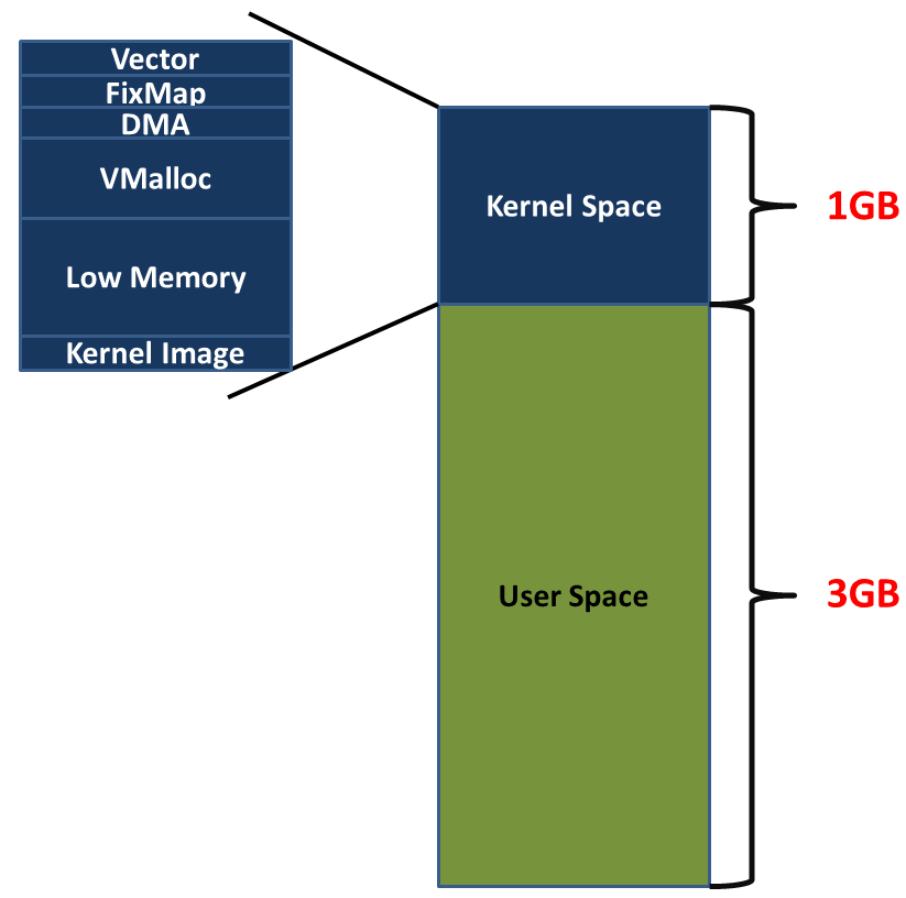
The entire virtual address space of the system on most computers is divided into two parts: the virtual address space for user mode program access (user spae) and the kernel space for kernel access. Whenever the kernel executes a context switch, the user layer part of the virtual address space will switch, so that the currently running process matches, and the kernel space will not switch.
For ordinary user processes, mm points to the user space part of the virtual address space, while for kernel threads, mm is NULL
.
Unlike user processes,
- Kernel threads run only in Kernel Mode they do not have any address space mapped,
- Kernel threads use only linear addresses greater than PAGE_OFFSET(3G on traditional x86_32) By default, kernel uses the top 1GB of virtual address.
Regular processes, on the other hand, use all 4 GB of linear addresses, in either User Mode or Kernel Mode.


There are two main types of kernel threads:
- After the thread is started, it waits until the kernel requests the thread to perform a specific operation.
- After the thread is started, it runs at periodic intervals, detects the use of specific resources, and takes action when the usage exceeds or falls below the preset limit.
Creating a kernel thread
The kernel_thread( ) function creates a new kernel thread.
/*
 * Create a kernel thread.
 */
pid_t kernel_thread(int (*fn)(void *), void *arg, unsigned long flags)
{
 struct kernel_clone_args args = {
  .flags  = ((flags | CLONE_VM | CLONE_UNTRACED) & ~CSIGNAL),
  .exit_signal = (flags & CSIGNAL),
  .stack  = (unsigned long)fn,
  .stack_size = (unsigned long)arg,
 };

 return _do_fork(&args);
}
The function essentially invokes _do_fork() with:- The CLONE_VM flag avoids the duplication of the page tables of the calling process: this duplication would be a waste of time and memory, because the new kernel thread will not access the User Mode address space anyway.
- The CLONE_UNTRACED flag ensures that no process will be able to trace the new kernel thread, even if the calling process is being traced.
If this function terminates, the kernel thread executes the _exit() system call

Process 0
The ancestor of all processes is called process 0, the idle process, or the swapper process(for historical reasons). This is a kernel thread created from scratch during the initialization phase of Linux
The start_kernel( ) function initializes all the data structures needed by the kernel, enables interrupts, and creates another kernel thread, named process 1 (more commonly referred to as the init process):
kernel_thread(init, NULL, CLONE_FS|CLONE_SIGHAND);
After having created the init process, process 0 executes the cpu_idle( ) function, which essentially consists of repeatedly executing the hlt assembly language instruction with the interrupts enabled.
Process 0 is selected by the scheduler only when there are no other processes in the TASK_RUNNING state.
In multiprocessor systems there is a process 0 for each CPU.
Right after the power-on, the BIOS of the computer starts a single CPU while disabling the others.
The swapper process running on CPU 0 initializes the kernel data structures, then enables the other CPUs and creates the additional swapper processes by means of the copy_process() function passing to it the value 0 as the new PID.
Moreover, the kernel sets the cpu field of the thread_info descriptor of each forked process to the proper CPU index.
Process 1
init( ) invokes the execve() system call to load the executable program init(systemd currently).
As a result, the init kernel thread becomes a regular process having its own per-process kernel data structure.
The init process stays alive until the system is shut down, because it creates and monitors the activity of all processes that implement the outer layers of the operating system.
Other kernel threads
Linux uses many other kernel threads. Some of them are created in the initialization phase and run until shutdown; others are created “on demand”. A few examples of kernel threads (besides process 0 and process 1) are:
- keventd (also called events) Executes the functions in the keventd_wq workqueue .
- kapmd Handles the events related to the Advanced Power Management (APM).
- kswapd Reclaims memory
- pdflush Flushes “dirty” buffers to disk to reclaim memory
- kblockd Executes the functions in the kblockd_workqueue workqueue.
- ksoftirqd Runs the tasklets there is one of these kernel threads for each CPU in the system.
Essentially, it periodically activates the block device drivers
CHAPTER 4 Interrupts and Exceptions. p.131
Interrupts are usually defined as events which are electrical signals generated by hardware circuits both inside and outside the CPU chip.
Interrupts are often divided into:
- synchronous Synchronous interrupts are produced by the CPU.
- asynchronous Asynchronous interrupts are generated by other hardware devices.
Intel calls these exceptions.
The Role of Interrupt Signals
When an interrupt signal arrives, the CPU must stop what it’s currently doing and switch to a new activity; it does this by:
- saving the current value of the program counter (i.e., the content of the eip and cs registers) in the Kernel Mode stack
- placing an address of the interrupt handler into the program counter
The code executed by an interrupt or by an exception handler is not a process, it is a kernel control path or separate sequence of instructions that execute in Kernel Mode on behalf of the current process.
Interrupt handling is one of the most sensitive tasks performed by the kernel:
- Interrupts can come anytime The activities that the kernel needs to perform in response to an interrupt are thus divided into a critical urgent part that the kernel executes right away(top-half handler) and a deferrable(bottom-half) part that is left for longer processing later.
- the interrupt handlers must be coded so that the corresponding kernel control paths can be executed in a nested manner When the last kernel control path terminates, the kernel must be able to resume execution of the interrupted process or switch to another process if the interrupt signal has caused a rescheduling activity.
- some critical regions must disable interrupts
Interrupts and Exceptions
The Intel documentation classifies interrupts and exceptions as follows:
- Interrupts
- Maskable interrupts All Interrupt Requests (IRQs) issued by I/O devices are maskable interrupts. A masked interrupt is ignored by CPU.
- Nonmaskable interrupts critical events (such as hardware failures)
- Exceptions
- Processor-detected exceptions Generated when the CPU detects an abnormal condition while executing an instruction.
- Faults Can generally be corrected, for ex., “Page Fault Exception Handler”. The saved value of eip is the address of the instruction that caused the fault, and hence that instruction can be resumed when the exception handler terminates.
- Traps The saved value of eip is the address of the instruction that should be executed after the one that caused the trap. The main use of traps is for debugging purposes.
- Aborts A serious error occurred. This handler has no choice but to force the affected process to terminate.
- Programmed exceptions Occur at the request of the programmer.They are triggered by instructions:
- int
- int3
- into (check for overflow)
- bound (check on address bound)
The vector is a memory location at which the address of the ISR can be found.
An interrupt vector table (IVT) is a data structure that associates a list of interrupt handlers with a list of interrupt requests in a table of interrupt vectors.

INT n: Calls ISR located at vector n (n*4).
IRQs and Interrupts
Each hardware device controller capable of issuing interrupt requests usually has a single output line designated as the Interrupt ReQuest (IRQ) line.
All existing IRQ lines are connected to the input pins of a hardware circuit "Programmable Interrupt Controller"(PIC), which performs the following actions:
- Monitors the IRQ lines If two or more IRQ lines are raised, PIC selects the one having the lower pin number.
- If a raised signal occurs on an IRQ line
- PIC converts the raised signal received into a corresponding interrupt vector
- PIC Stores the vector in an Interrupt Controller I/O port for the CPU to read
- PIC issues an interrupt Sends a raised signal to the processor INTR pin
- Waits until the CPU acknowledges the interrupt signal One of the PIC's I/O ports will be written by CPU
- clears the INTR line
The Advanced Programmable Interrupt Controller (APIC)
If the system includes a single CPU, the output line of the master PIC can be connected in a straightforward way to the INTR pin the CPU.
Being able to deliver interrupts to each CPU in the SMP architecture system , all current 80 × 86 microprocessors include a local APIC. All local APICs are connected to an external I/O APIC, giving rise to a multi-APIC system.

The I/O APIC consists of a set of 24 IRQ lines.
Interrupt requests coming from external hardware devices are distributed among the available CPUs
Besides distributing interrupts among processors, the multi-APIC system allows CPUs to generate interprocessor interrupts.
Exceptions
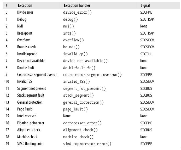
The 80×86 microprocessors issue roughly 20 different exceptions. The kernel must provide a dedicated exception handler for each exception type.
The following list (80×86 processors) gives the vector number, the exception name, the exception handler, and the signal sent to the process that caused the exception:
Interrupt Descriptor Table
A system table called Interrupt Descriptor Table (IDT) associates each interrupt or exception vector with the address of the corresponding interrupt or exception handler.
Each entry in IDT uses 8 bytes. Thus, a maximum of 256×8=2048 bytes are required to store the IDT.
The idtr CPU register allows the IDT to be located. It must be initialized before enabling interrupts by using the lidt assembly language instruction.
The IDT may include three types of descriptors:
- Task gate
- Interrupt gate
- Trap gate
Hardware Handling of Interrupts and Exceptions
Nested Execution of Exception and Interrupt Handlers
Initializing the Interrupt Descriptor Table
Interrupt, Trap, and System Gates
Preliminary Initialization of the IDT
Exception Handling
Most exceptions issued by the CPU are interpreted by Linux as error conditions.
When one of them occurs, the kernel sends a signal to the process that caused the exception to notify it of an anomalous condition.
Exception handlers have a standard structure consisting of three steps:
- Save the contents of most registers in the Kernel Mode stack (this part is coded in assembly language).
- Handle the exception by means of a high-level C function.
- Exit from the handler by means of the ret_from_exception( ) function.
IDT entries that refer to nonmaskable interrupts and exceptions.
set_trap_gate(0,÷_error); set_trap_gate(1,&debug); set_intr_gate(2,&nmi); set_system_intr_gate(3,&int3); set_system_gate(4,&overflow); set_system_gate(5,&bounds); set_trap_gate(6,&invalid_op); set_trap_gate(7,&device_not_available); set_task_gate(8,31); set_trap_gate(9,&coprocessor_segment_overrun); set_trap_gate(10,&invalid_TSS); set_trap_gate(11,&segment_not_present); set_trap_gate(12,&stack_segment); set_trap_gate(13,&general_protection); set_intr_gate(14,&page_fault); set_trap_gate(16,&coprocessor_error); set_trap_gate(17,&alignment_check); set_trap_gate(18,&machine_check); set_trap_gate(19,&simd_coprocessor_error); set_system_gate(128,&system_call);
Each exception handler will load the address of the high-level C function and execute it.
Most of these C functions invoke the do_trap() function to store the hardware error code and the exception vector in the process descriptor of current , and then send a suitable signal to that process:
current->thread.error_code = error_code;
current->thread.trap_no = vector;
force_sig(sig_number, current);
Interrupt Handling
The kernel is able to process the exception quickly because most exceptions are handled simply by sending a Unix signal to the process that caused the exception..
Interrupt handling depends on the type of interrupt:
- I/O interrupts the corresponding interrupt handler must query the device to determine the proper course of action.
- Timer interrupts this kind of interrupt tells the kernel that a fixed-time interval has elapsed.
- Interprocessor interrupts
I/O Interrupt Handling
In general, an I/O interrupt handler must be flexible enough to service several devices at the same time.
Interrupt handler flexibility is achieved in two distinct ways:
- IRQ sharing The interrupt handler executes several interrupt service routines (ISRs). Each ISR is executed to verify whether its device needs attention then performs operations.
- IRQ dynamic allocation An IRQ line is associated with a device driver when necessary( at the last possible moment ). In this way, the same IRQ vector may be used by several hardware devices.
Linux divides the actions to be performed following an interrupt into three classes:
- Critical Actions can be executed quickly and are critical. Critical actions are executed within the interrupt handler immediately, with maskable interrupts disabled.
- Noncritical These actions can also finish quickly, so they are executed by the interrupt handler immediately, with the maskable interrupts enabled.
- Noncritical deferrable Noncritical defer rable actions are performed by means of separate functions that are discussed in the later section “Softirqs and Tasklets.”
All I/O interrupt handlers perform the same four basic actions:
- Save the IRQ value and the register’s contents on the Kernel Mode stack.
- Send an acknowledgment to the PIC that is servicing the IRQ line, thus allowing it to issue further interrupts.
- Execute the interrupt service routines (ISRs) associated with all the devices that share the IRQ.
- Terminate by jumping to the ret_from_intr( ) address.

Physical IRQs may be assigned any vector in the range 32–238. However, Linux uses vector 128 to implement system calls.
The IBM-compatible PC architecture requires that some devices be statically connected to specific IRQ lines:
- The interval timer device must be connected to the IRQ#0
- The slave 8259A PIC must be connected to the IRQ#2
- The external mathematical coprocessor must be connected to the IRQ#13
- An I/O device can be connected to a limited number of IRQ lines

There are three ways to select a line for an IRQ-configurable device:
- By setting hardware jumpers (only on very old device cards).
- By a utility program shipped with the device and executed when installing it. Such a program may either ask the user to select an available IRQ number or probe the system to determine an available number by itself.
- By a hardware protocol(PCI) executed at system startup.
NR_IRQS is platform dependent . arch/x86/include/asm/irq_vectors.h:
#define NR_VECTORS    256

#define NR_IRQS_LEGACY   16

#define CPU_VECTOR_LIMIT  (64 * NR_CPUS)
#define IO_APIC_VECTOR_LIMIT  (32 * MAX_IO_APICS)

#if defined(CONFIG_X86_IO_APIC) && defined(CONFIG_PCI_MSI)
#define NR_IRQS      \
 (CPU_VECTOR_LIMIT > IO_APIC_VECTOR_LIMIT ? \
  (NR_VECTORS + CPU_VECTOR_LIMIT)  : \
  (NR_VECTORS + IO_APIC_VECTOR_LIMIT))
#elif defined(CONFIG_X86_IO_APIC)
#define NR_IRQS    (NR_VECTORS + IO_APIC_VECTOR_LIMIT)
#elif defined(CONFIG_PCI_MSI)
#define NR_IRQS    (NR_VECTORS + CPU_VECTOR_LIMIT)
#else
#define NR_IRQS    NR_IRQS_LEGACY
#endif
Every interrupt vector has its own irq_desc_t descriptor,

An interrupt is unexpected if it is not handled by the kernel, that is, either if there is no ISR associated with the IRQ line, or if no ISR associated with the line recognizes the interrupt as raised by its own hardware device.
The status of an IRQ line is described by the flags:

Whether the IRQ line is enabled or disabled is depended on the depth field and the IRQ_DISABLED flag:
- During system initialization, the init_IRQ() function sets the status field of each IRQ main descriptor to IRQ_DISABLED .
Softirqs and Tasklets. p.171
Non critical tasks can be deferred for a long period of time, if necessary. Taking them out of the interrupt handler helps keep
kernel response time small. The deferrable tasks can execute with all interrupts enabled.
Softirqs
CHAPTER 5 Kernel Synchronization. p.189
CHAPTER 8 Memory Management
Linux- takes advantage of 80 × 86’s segmentation and paging circuits to translate logical addresses into physical ones.
- some portion of RAM is permanently assigned to the kernel and used to store both the kernel code and the static kernel data structures.
- The remaining part of the RAM is called dynamic memory.

留言