Raspberry PI : GPIO kernel driver for interrupt management
GPIO
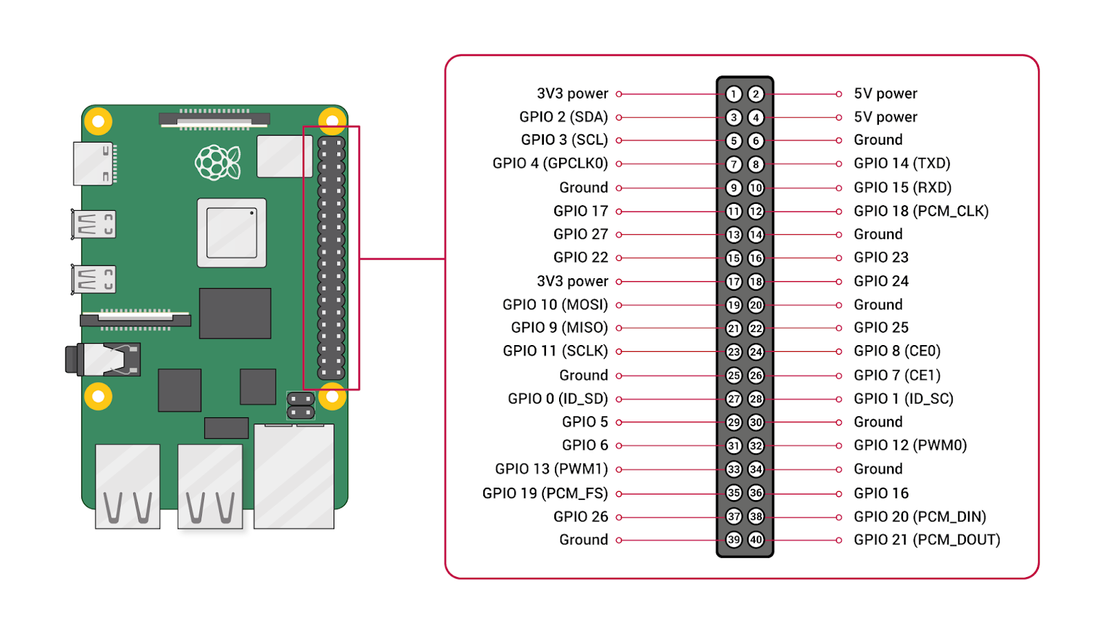

- Voltage Pins are not configurable 5V pins x 2, 3V3 pins x 2, as well as a number of ground pins (0V)
- specific pins
- Serial TX (GPIO14); RX (GPIO15)
- I2C
- Data (GPIO2); Clock (GPIO3)
- EEPROM Data (GPIO0); EEPROM Clock (GPIO1)
- PWM (pulse-width modulation) Hardware PWM available on GPIO12, GPIO13, GPIO18, GPIO19
- SPI
- SPI0: MOSI (GPIO10); MISO (GPIO9); SCLK (GPIO11); CE0 (GPIO8), CE1 (GPIO7)
- SPI1: MOSI (GPIO20); MISO (GPIO19); SCLK (GPIO21); CE0 (GPIO18); CE1 (GPIO17); CE2 (GPIO16)
- application pins GPIO4, GPIO5, GPIO6, GPIO22, GPIO23, GPIO24, GPIO25, GPIO26, GPIO27
The Linux driver implementer’s API guide: General Purpose Input/Output (GPIO)
Introduction
GPIO Interfaces
There are two different ways to obtain and use GPIOs:- The descriptor-based interface the preferred way to manipulate GPIOs
- The legacy integer-based interface deprecated (but still usable for compatibility reasons) and documented in gpio-legacy.txt.
What is a GPIO?
Each GPIO represents a bit connected to a particular pin.
Board schematics show which external hardware connects to which GPIOs.
Drivers can be written generically, so that board setup code passes such pin configuration data to drivers.
Usually a GPIO will be configurable as either input or output. Output values are writable (high=1, low=0). Inputs can often be used as IRQ signals, often edge triggered but sometimes level triggered.
Common GPIO Properties
The decision of "active-high" or "active-low" is transparent to device drivers.
Tri-state Logic
Most modern GPIO lines are implemented as a tri-state buffer. This means that the GPIO line can effectively assume three values:- Logical 0 (connection to ground)
- Logical 1 (connection to VCC)
- High-impedance (also called “floating”, “Hi-Z”, “tri-stated”)
Pull up vs Pull down
A pullup or pulldown resistor causes the high or low signal level.Why can't connect the digital logic pins directly to the Logic level voltage or with the ground ?

This just likes the short circuit and could damage the sensitive logic circuit.
- Pull up is placing a resistor between a signal and +V A Pull-up resistor is used to make the default state of the digital pin as High or to the logic level ( + 5/3.3 V).
- pull down is placing a resistor between a signal and ground. A Pull-Down resistor makes the default state of the digital pin as Low (0V).
 The digital logic input pin P0.5 can be toggled from logic 1 or High to the logic 0 or Low using the switch SW1. The logical input pin has always a default voltage of 5V or the pin is always High. When the switch is pressed, the pin is shorted to ground making it logic Low.
Push-pull vs Open-Drain
Microcontrollers use pins for interfacing with the outside world. In general, the pins are the physical points on the package of an integrated circuit (IC).
Behind each pin (inside the IC) there is a special circuitry used for driving it. This circuitry (usually called a pad) can be configured to allow the pin to interface with different types of digital and analog circuits.
The most common types of output configurations are:
- Push-Pull Push-pull is the most common output configuration. Push-pull output is capable of driving two output levels: One is pull to ground (pull/sink current from the load) and the other is push to power supply voltage (push/source current to the load). The push-pull output can be implemented using a pair of switches.
- Open Drain In open drain configuration, the logic behind the pin can drive it only to ground (logic 0). The other possible state is high impedance (Hi-Z). Open drain outputs are most commonly used in communication interfaces where multiple devices are connected on the same line (e.g I2C, One-Wire etc.). The line is driven to a default logic 1 level by a pull-up. Any device can pull the line to logic 0 using its open drain output and all devices can see this level.
 Push-pull configuration is most commonly used in interfaces that have unidirectional lines
Input and Output Modes
In general, there GPIO inputs are primarily configured in one of three ways:
- High-impedance (default – floats if not driven)
- Pull-up (internal resistor connected to VCC)
- Pull-down (internal resistor connected to Ground)
- push-pull
- open-drain
GPIO Descriptor Driver Interface
Each GPIO controller driver needs to include the following header, which defines the structures used to define a GPIO driver:
#include <linux/gpio/driver.h>
Internal Representation of GPIOs
Inside a GPIO driver, individual GPIOs are identified by their hardware number, which is a unique number between 0 and n, n being the number of GPIOs managed by the chip. This number is purely internal: the hardware number of a particular GPIO descriptor is never made visible outside of the driver.
On top of this internal number, each GPIO also need to have a global number in the integer GPIO namespace so that it can be used with the legacy GPIO interface. Each chip must thus have a “base” number (which can be automatically assigned), and for each GPIO the global number will be (base + hardware number).
A GPIO controller is abstracted by struct gpio_chip defined in linux/gpio/driver.h:
struct gpio_chip {
 const char  *label;
 struct gpio_device *gpiodev;
 struct device  *parent;
 struct module  *owner;

 int   (*request)(struct gpio_chip *chip,
      unsigned offset);
 void   (*free)(struct gpio_chip *chip,
      unsigned offset);
 int   (*get_direction)(struct gpio_chip *chip,
      unsigned offset);
 int   (*direction_input)(struct gpio_chip *chip,
      unsigned offset);
 int   (*direction_output)(struct gpio_chip *chip,
      unsigned offset, int value);
 int   (*get)(struct gpio_chip *chip,
      unsigned offset);
 int   (*get_multiple)(struct gpio_chip *chip,
      unsigned long *mask,
      unsigned long *bits);
 void   (*set)(struct gpio_chip *chip,
      unsigned offset, int value);
 void   (*set_multiple)(struct gpio_chip *chip,
      unsigned long *mask,
      unsigned long *bits);
 int   (*set_config)(struct gpio_chip *chip,
           unsigned offset,
           unsigned long config);
 int   (*to_irq)(struct gpio_chip *chip,
      unsigned offset);
 void   (*dbg_show)(struct seq_file *s,
      struct gpio_chip *chip);
 int   (*init_valid_mask)(struct gpio_chip *chip,
         unsigned long *valid_mask,
         unsigned int ngpios);
 int   (*add_pin_ranges)(struct gpio_chip *chip);
 int   base;
 u16   ngpio;
 const char  *const *names;
 bool   can_sleep;
...
};
This structure provides:-
methods to establish GPIO line direction
methods used to access GPIO line values
method to set electrical configuration to a a given GPIO line
method to return the IRQ number associated to a given GPIO line
flag saying whether calls to its methods may sleep
optional line names array to identify lines
optional debugfs dump method (showing extra state like pullup config)
optional base number (will be automatically assigned if omitted)
optional label for diagnostics and GPIO chip mapping using platform data
- register a gpio_chip Use gpiochip_add_data() or devm_gpiochip_add_data().
- Removing a GPIO controller should be rare Use devm_gpiochip_remove() when it is unavoidable.
GPIOs can be configured for several electrical modes of operation by using the set_config() callback.
Programming with GPIO
GPIO with C/C++ using standard kernel interface via libgpiod
configure: error: "libgpiod needs linux headers version >= v5.5.0"
Raspberry Pi GPIO: frequency measurement
The easiest way is to measure the time elapsing between two successive interrupts triggered by rising edges and calculate the reverse.
Principle
The driver installs a handler on each interrupt line concerned and measures at each rising edge the time elapsed since the last triggering of the same signal. The durations are obtained in microseconds. The frequency calculation in Hz will therefore be done by dividing 1,000,000 by the duration measured.
To use the compiled kernel module, gpio-freq.ko, you must provide the parameter "gpios" to indicate the list of GPIOs whose frequency you want to measure. for example
# insmod gpio-freq.ko gpios = 16,22,23,17
To make the calculated frequencies accessible, the driver provides special device files corresponding to the different GPIOs requested:
/dev/gpiofreqNN/dev/gpiofreq0 being the first in the list, /dev/gpiofreq1the next, and so on.
Implementation
- Makefile
ifneq (${KERNELRELEASE},)

 obj-m  = gpio-freq.o
else

 MODULE_DIR := $(shell pwd)
 KERNEL_DIR ?= /lib/modules/$(shell uname -r)/build

# KERNEL_DIR = /usr/local/src/linux-rpi-3.6.11
# ARCH       = arm
# CROSS_COMPILE = /usr/local/cross/rpi/bin/arm-linux-

 CFLAGS := -Wall -g

all: modules

modules:
 ${MAKE} -C ${KERNEL_DIR} SUBDIRS=${MODULE_DIR}  modules

clean:
 rm -f *.o *.ko *.mod.c .*.o .*.ko .*.mod.c .*.cmd *~
 rm -f Module.symvers Module.markers modules.order
 rm -rf .tmp_versions

endif
/***************************************************************************\

 Raspberry Pi GPIO frequency measurement.

 Copyright (c) 2014 Christophe Blaess

 This program is free software; you can redistribute it and/or modify it
 under the terms of the GNU General Public License version 2 as published by
 the Free Software Foundation.

\***************************************************************************/

#include <linux/cdev.h>
#include <linux/device.h>
#include <linux/fs.h>
#include <linux/gpio.h>
#include <linux/interrupt.h>
#include <linux/module.h>
#include <linux/sched.h>
#include <linux/slab.h>
#include <linux/spinlock.h>
#include <linux/version.h>

#include <asm/uaccess.h>


// ------------------ Default values ----------------------------------------

#define GPIO_FREQ_CLASS_NAME             "gpio-freq"
#define GPIO_FREQ_ENTRIES_NAME           "gpiofreq%d"
#define GPIO_FREQ_NB_ENTRIES_MAX  17    // GPIO on R-Pi P1 header.

//------------------- Module parameters -------------------------------------

 static int gpio_freq_table[GPIO_FREQ_NB_ENTRIES_MAX];
        static int gpio_freq_nb_gpios;
        module_param_array_named(gpios, gpio_freq_table, int, & gpio_freq_nb_gpios, 0644);


// ------------------ Driver private data type ------------------------------

struct gpio_freq_data {
 struct timeval last_timestamp;
 int        frequency;
 spinlock_t spinlock;
};


// ------------------ Driver private methods -------------------------------

static irqreturn_t gpio_freq_handler(int irq, void * filp);

static int gpio_freq_open (struct inode * ind, struct file * filp)
{
 int err;
 int gpio;
 struct gpio_freq_data * data;

 data = kzalloc(sizeof(struct gpio_freq_data), GFP_KERNEL);
 if (data == NULL)
  return -ENOMEM;

 spin_lock_init(& (data->spinlock));

 gpio = iminor(ind);
 err = gpio_request(gpio_freq_table[gpio], THIS_MODULE->name);
 if (err != 0) {
  printk(KERN_ERR "%s: unable to reserve GPIO %d\n", THIS_MODULE->name, gpio_freq_table[gpio]);
  kfree(data);
  return err;
 }

 err = gpio_direction_input(gpio_freq_table[gpio]);
 if (err != 0) {
  printk(KERN_ERR "%s: unable to set GPIO %d as input\n", THIS_MODULE->name, gpio_freq_table[gpio]);
  gpio_free(gpio_freq_table[gpio]);
  kfree(data);
  return err;
 }

 err = request_irq(gpio_to_irq(gpio_freq_table[gpio]), gpio_freq_handler,
                   IRQF_SHARED | IRQF_TRIGGER_RISING,
                   THIS_MODULE->name, filp);
 if (err != 0) {
  printk(KERN_ERR "%s: unable to handle GPIO %d IRQ\n", THIS_MODULE->name, gpio_freq_table[gpio]);
  gpio_free(gpio_freq_table[gpio]);
  kfree(data);
  return err;
 }

 filp->private_data = data;
 return 0;
}


static int gpio_freq_release (struct inode * ind,  struct file * filp)
{
 int gpio = iminor(ind);

 free_irq(gpio_to_irq(gpio_freq_table[gpio]), filp);

 gpio_free(gpio_freq_table[gpio]);

 kfree(filp->private_data);

 return 0;
}


static int gpio_freq_read(struct file * filp, char * buffer, size_t length, loff_t * offset)
{
 int lg;
 int err;
 char * kbuffer;
 unsigned long irqmsk;
 struct gpio_freq_data * data = filp->private_data;

 kbuffer = kmalloc(128, GFP_KERNEL);
 if (kbuffer == NULL)
  return -ENOMEM;

 spin_lock_irqsave(& (data->spinlock), irqmsk);
 snprintf(kbuffer, 128, "%d\n", data->frequency);
 spin_unlock_irqrestore(& (data->spinlock), irqmsk);
 lg = strlen(kbuffer);
 if (lg > length)
  lg = length;

 err = copy_to_user(buffer, kbuffer, lg);

 kfree(kbuffer);

 if (err != 0)
  return -EFAULT;
 return lg;
}


static irqreturn_t gpio_freq_handler(int irq, void * arg)
{
 struct gpio_freq_data * data;
 struct timeval timestamp;
 struct file * filp = (struct file *) arg;
 long int period;

 do_gettimeofday(& timestamp);

 if (filp == NULL)
  return -IRQ_NONE;

 data = filp->private_data;
 if (data == NULL)
  return IRQ_NONE;

 if ((data->last_timestamp.tv_sec  != 0)
  || (data->last_timestamp.tv_usec != 0)) {
  period  = timestamp.tv_sec - data->last_timestamp.tv_sec;
  period *= 1000000;  // In microsec.
  period += timestamp.tv_usec - data->last_timestamp.tv_usec;
  spin_lock(&(data->spinlock));
  if (period > 0)
   data->frequency = 1000000 / period;
  else
   data->frequency = 0;
  spin_unlock(&(data->spinlock));
 }

 data->last_timestamp = timestamp;

 return IRQ_HANDLED;
}


// ------------------ Driver private global data ----------------------------

static struct file_operations gpio_freq_fops = {
 .owner   =  THIS_MODULE,
 .open    =  gpio_freq_open,
 .release =  gpio_freq_release,
 .read    =  gpio_freq_read,
};


 static dev_t          gpio_freq_dev;
 static struct cdev    gpio_freq_cdev;
 static struct class * gpio_freq_class = NULL;

// ------------------ Driver init and exit methods --------------------------

static int __init gpio_freq_init (void)
{
 int err;
 int i;

 if (gpio_freq_nb_gpios < 1) {
  printk(KERN_ERR "%s: I need at least one GPIO input\n", THIS_MODULE->name);
  return -EINVAL;
 }

 err = alloc_chrdev_region(& gpio_freq_dev, 0, gpio_freq_nb_gpios, THIS_MODULE->name);
 if (err != 0)
  return err;

 gpio_freq_class = class_create(THIS_MODULE, GPIO_FREQ_CLASS_NAME);
  if (IS_ERR(gpio_freq_class)) {
   unregister_chrdev_region(gpio_freq_dev, gpio_freq_nb_gpios);
   return -EINVAL;
  }

 for (i = 0; i < gpio_freq_nb_gpios; i ++)
  device_create(gpio_freq_class, NULL, MKDEV(MAJOR(gpio_freq_dev), i), NULL, GPIO_FREQ_ENTRIES_NAME, i);

 cdev_init(& gpio_freq_cdev, & gpio_freq_fops);

 err = cdev_add(& (gpio_freq_cdev), gpio_freq_dev, gpio_freq_nb_gpios);
 if (err != 0) {
  for (i = 0; i < gpio_freq_nb_gpios; i ++)
   device_destroy(gpio_freq_class, MKDEV(MAJOR(gpio_freq_dev), i));
  class_destroy(gpio_freq_class);
  unregister_chrdev_region(gpio_freq_dev, gpio_freq_nb_gpios);
  return err;
 }

 return 0;
}


void __exit gpio_freq_exit (void)
{
 int i;

 cdev_del (& gpio_freq_cdev);

 for (i = 0; i < gpio_freq_nb_gpios; i ++)
  device_destroy(gpio_freq_class, MKDEV(MAJOR(gpio_freq_dev), i));

 class_destroy(gpio_freq_class);
 gpio_freq_class = NULL;

 unregister_chrdev_region(gpio_freq_dev, gpio_freq_nb_gpios);
}


module_init(gpio_freq_init);
module_exit(gpio_freq_exit);

MODULE_LICENSE("GPL");
MODULE_AUTHOR("christophe.blaess@logilin.fr");
Raspberry PI : GPIO kernel driver for interrupt management
This post is about how to compile a kernel driver for directly handling the interrupts from devices.
RF-433

這種 RF Link 模組沒有錯誤檢查功能, 無法確認送出的資料是否正確接收. 注意, 接收板中間的兩個針腳是相同的 Data 腳, 接哪一個都可以. 另外, 兩塊板子上都有一個 ANT 天線孔, 可以用單心線繞原子筆捲成一個 2cm 的彈簧天線, 一端焊在 ANT 孔上才能讓傳送距離增加, 參考商品說明 :
"使用前,發射與接收端都要接上天線,以達到最佳接收效果; 天線可以用單心線捲成螺旋狀,長度約2公分即可。"
沒有天線的話傳遞距離大約只有 40~50 公分而已, 加上天線空曠處可達 40 公尺 (書上說可達 100 公尺),
發射距離 20~200 公尺 ("不同電壓不同距離"), 原來此種模組可工作於 3.5V~12V 電壓, 所以 200 公尺或許是在 12V 下於空曠地方才有這樣的傳送距離. 難怪這種便宜的模組常用在玩具車, 遙控飛機, 鐵捲門, 防盜器, 汽機車遙控車門啟閉等應用裡, 且常用 12V 的乾電池 (小圓筒形或方形).
Be prepared to compile a kernel module
- Update your distribution and install needed packages
- Clone the kernel repo
- # cd rpi-kernel; head Makefile
- # uname -a
- copy the run-time kernel configuration into the downloaded source This step is not necessary for the latest version.
- Build the kernel, modules,device tree blobs
- Install modules
- Install the built kernel and reboot kernel is the alternative filename on the boot partition to use when loading the kernel. The default value:
- kernel.img For the Pi 1, Pi Zero, and Compute Module
- kernel7.img For the Pi 2, Pi 3, and Compute Module 3
- kernel7l.img For the Pi4
- kernel8.img This 64-bit kernel will only work on the Pi4, Pi3, and Pi2B rev1.2 boards with latest firmware.
- Check the booted kernel version
# sudo apt-get update
# sudo apt-get upgrade
sudo apt install libncurses5-dev bison flex
# sudo apt-get install bc
# git clone http://github.com/raspberrypi/linux rpi-kernel

(git clone --depth=1 https://github.com/raspberrypi/linux )
Check if your kernel version match the one cloned:
# zcat /proc/config.gz > ./.configOr, do it manually:
cd linux
KERNEL=kernel7
make bcm2709_defconfig
# make -j4 ; make modules
make modules_install
# sudo cp /boot/kernel7l.img /boot/kernel7l.old
# sudo cp arch/arm/boot/zImage /boot/kernel7.img
# reboot
Or,
sudo cp arch/arm/boot/dts/*.dtb /boot/
sudo cp arch/arm/boot/dts/overlays/*.dtb* /boot/overlays/
sudo cp arch/arm/boot/dts/overlays/README /boot/overlays/
sudo scripts/mkknlimg arch/arm/boot/zImage /boot/$KERNEL.img
# uname -a

留言