ARM SMMU
Mastering the DMA and IOMMU APIs
Embedded Linux Conference 2014 San Jose Laurent Pinchart laurent.pinchart@ideasonboard.comMemory Access Hardware
- CPU writes to memory
- Device reads from memory

CPU Write Buffer

- CPU writes to memory
- CPU flushes its write buffers
- Device reads from memory
CPU Write Cache

Cache memory is an extremely fast memory type that acts as a buffer between RAM and the CPU.
It holds frequently requested data and instructions so that they are immediately available to the CPU when needed.
L1 Cache
It is a type of memory in which data is stored and accepted that are immediately stored in CPU.Most commonly used register is accumulator, Program counter, address register etc.

- CPU writes to memory
- CPU cleans L1 cache
- Device reads from memory
L2 Cache
It is the fastest memory which has faster access time where data is temporarily stored for faster access.
- CPU writes to memory
- CPU cleans L1 cache
- CPU cleans L2 cache
- Device reads from memory
cache Mapping
There are three different types of mapping used for the purpose of cache memory :- Direct Mapping
- Associative Mapping
- Set-associative Mapping
Cache Coherent Interconnect

- CPU writes to memory
- Device reads from memory
IOMMU

- CPU writes to memory
- CPU programs the IOMMU
- Device reads from memory
More Complex System Architecture


Memory Mappings
Coherent (or consistent) memory is memory for which a write by either the device or the processor can immediately be read by the processor or device without having to worry about caching effects.Fully consistent memory can be expensive.
Cache Management
Cache management operations are architecture and device specific.To remain portable, device drivers must not use the cache handling API directly.
DMA mapping and DMA engine
DMA Mapping API
- Allocate memory suitable for DMA operations
- Map DMA memory to devices
- Map DMA memory to userspace
- Synchronize memory between CPU and device domains
#include <linux/dma-mapping.h>

linux/dma-mapping.h
│├
─ linux/dma-attrs.h
├─ linux/dma-direction.h
├─ linux/scatterlist.h
├─ linux/scatterlist.h
#ifdef CONFIG_HAS_DMA
└─ asm/dma-mapping.h
#else
└─ asm-generic/dma-mapping-broken.h
#endif
│─ arch/arm/include/asm/dma-mapping.h
│
├─ asm-generic/dma-mapping-common.h
└─ asm-generic/dma-coherent.h
Contiguous Memory Allocation
The Contiguous Memory Allocator (CMA) is integrated in the DMA mapping implementation.Drivers will automatically receive contiguous memory when using the dma_alloc_coherent() and dma_alloc_attrs() API.
IOMMU Integration
Device Tree Bindings
Device Tree support for CMA (Contiguous Memory Allocator): http://lwn.net/Articles/564830/
DMA
Direct memory access (DMA) is a feature of computer systems that allows certain hardware subsystems to access main system memory independently of the central processing unit (CPU).
The DMA controller/device can act as a bus master and can read and write physical memory.
With DMA, the CPU first initiates the transfer, then it does other operations while the transfer is in progress, and it finally receives an interrupt from the DMA controller (DMAC) when the operation is done.
To initiate a DMA copy operation, software first writes a physical address to the DMA source and DMA destination registers.
To start the copy operation, the software writes the DMA control register.
Input–output memory management unit(IOMMU)

Some units also provide memory protection from faulty or malicious devices.
The advantages of having an IOMMU:
- the IOMMU maps contiguous virtual addresses to the underlying fragmented physical addresses.
- Devices that do not support memory addresses long enough to address the entire physical memory can still address the entire memory through the IOMMU
This makes providing direct access to the computer hardware difficult, because if the guest OS tried to instruct the hardware to perform a direct memory access (DMA) using guest-physical addresses, it would likely corrupt the memory, as the hardware does not know about the mapping between the guest-physical and host-physical addresses for the given virtual machine.
The corruption can be avoided if the hypervisor or host OS intervenes in the I/O operation to apply the translations. However, this approach incurs a delay in the I/O operation.
An IOMMU solves this problem by re-mapping the addresses accessed by the hardware according to the same (or a compatible) translation table that is used to map guest-physical address to host-physical addresses.
ARM defines its version of IOMMU as System Memory Management Unit (SMMU) to complement its Virtualization architecture.

Introduction to IOMMU and ARM SMMU
Introduction to the IOMMU
Like a traditional MMU, the IOMMU maps device-visible virtual addresses (also called I/O virtual address, IOVA) to physical addresses (PAs).Different platforms have different IOMMUs, such as the Intel IOMMU graphics address remapping table (GART) used by PCI Express graphics cards, and System Memory Management Unit (SMMU) used by the ARM platform.

- Large regions of memory can be allocated without the need to be contiguous in physical memory. The IOMMU maps contiguous VAs to the fragmented PAs.
- Devices that do not support memory addresses long enough to address the entire physical memory can still address the entire memory through the IOMMU. For example, x86 processors can address more than 4 GB of memory with the Physical Address Extension (PAE) feature.
- Memory is protected from malicious devices that are attempting DMA attacks and faulty devices that are attempting errant memory transfers. because a device cannot read or write to the mapped physical memory
But an ordinary 32-bit PCI device cannot address the memory above 4 GB. With IOMMU, the device can address the entire physical memory.
ARM SMMU Data Structure
The SMMU provides the capability of accessing the physical memory by using the IOVA visible to the device.The SMMU uses a set of data structures in memory to locate translation data.
SMMU_(*_)STRTAB_BASE hold the base address of the initial structure, the Stream Table.
- The SMMU needs to distinguish different client devices, so each device is assigned with a stream ID (SID), which points to the corresponding Stream Table Entry (STE).
- Common configuration
- Stage 1 translation settings
- S1Fmt: format of the CD table
- S1ContextPtr: stage 1 Context descriptor pointer
- S1CDMax: number of CDs pointed by S1ContextPtr
- S1DSS: default substream
- S1CIR/S1COR/S1CSH: CD table memory attributes
- Stage 2 translation settings
- S2T0SZ: size of IPA covered by stage 2 translation table
- S2SL0: starting level of stage 2 translation table walk
- S2IR0/S2OR0/S2SH0: memory attributes of stage 2 translation table walk
- S2TG: stage 2 Translation Granule size
- S2PS: physical address size
Substreams enable transactions from the same device to share the same stage 2 translation, but have different stage 1 translations. All configurations for the device to access the memory through the SMMU are written into the STE corresponding to the SID.
The following list lists some commonly used fields:

If an STE points to an array of several CDs, an incoming SubstreamID selects one of the CDs and therefore the SubstreamID determines which stage 1 translations are used by a transaction.


ARM SMMU
- DMA:((Direct Memory Access) 是一種外部設備不通過CPU而直接與系統memory交換數據的接口技術 。
- 虛擬化 在虛擬化場景, 所有的VM都運行在中間層hypervisor上,每一個VM獨立運行自己的OS(guest OS),Hypervisor完成硬體資源的共享, 隔離和切換。
外設可以通過DMA,將數據批量傳輸到memory,然後再發送一個中斷通知CPU取,其傳輸過程並不經過CPU, 減輕了CPU的負擔。
但由於DMA不能像CPU一樣通過MMU操作虛擬地址,所以DMA需要連續的物理地址。

SMMU翻譯過程需要使用多種data structure,如STE, CD,PTW等.
Stream Table Entry, STE裡面包含一個指向stage2地址翻譯表的pointer,並且同時還包含一個指向CD(Context Descriptor)的pointer.

Stream Table是存放在記憶體中的一張表,在SMMU驅動初始化時由驅動程式建立好。 STRTAB_BASE定義了STE的基地值
Stream table有兩種格式 :
- Linear Stream Table
- 2-level Stream Table
- 則先通過sid的高位找到L1_STD(STRTAB_BASE + sid[9:8] * 8, 一個L1_STD的大小為8B), L1_STD定義了下一級查詢的基地址
- 然後通過sid 找到具體的STE(l2ptr + sid[7:0] * 64)

Linear Stream Table 實現簡單,只需要一次索引,速度快;但是平臺上外設較少時,浪費連續的記憶體空間。
STRTAB_BASE + sid * 64(一個STE的大小為64B)找到Stream id 的STE.

第二級STE是Linear stream Table.
2-level Stream Table的優點是更加節省記憶體。
若使用2-level查詢,
SMMU跟TrustZone的關係?
在實際的項目中有些Master也是要存取 Secure Memory的,例如DPU,DMA等。TrustZone的基本原理是將系統資源劃分成安全的和非安全的兩部分,CPU本身支持TrustZone,可以發出安全存取和非安全存取。
但是SoC的其他Master也需要存取 memory,在有些場景下也需要存取安全的memory和非安全的memory,那該怎麼去實現呢?

但是第三方的Master可能不支持TrustZone,可以在IP前面加安全控制器來實現,例如這個控制器是Secure only的,可以通過TEE對安全控制器進行編程,Master發出的存取不Care安全或者非安全,通過控制器來擴展TrustZone功能,但是這種方式很大局限性;另外一種方法就是我們可以今天介紹的SMMU來實現。
SMMU是Arm的System IP,幾乎是跟CPU演進結合最緊密的一個IP。
我們知道CPU內部有個MMU,SMMU(System MMU)就是跟MMU非常相似,是主要給其他的Master來使用,連page table格式也是一樣的,只是編程方式不同,理論上可以讓CPU的MMU和SMMU可以使用同一套page table。

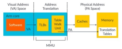
- 一部分是TLB用來Cache VA和PA間的轉換關係
- 一部分是Table Walk Unit,如果TLB裡沒有找到VA和PA的轉換關係,該Table Walk Unit就從page table裡查詢VA和PA的轉換關係。
- 會自動通過streamid檢索到streamid對應的STE(Stream Table Entry) table
- 再通過substreamid檢索到這個STE table指向的CD(context descriptor) table
- 從CD表中找到頁表基地址(page table base address)
- 開始頁表查找過程
- 找到IO VA對應的PA
- 再對這個PA發起一次DMA請求
SMMU硬件會自動清除其內部的TLB buffer對應項,達到與MMU同步的作用。該機制是ARM系統結構下SVA(shared virtual addressing)的基礎,即SMMU與MMU共享頁表,設備可以看到和CPU相同的VA,設備也就能“理解”各種進程虛擬內存的語義。
一個SMMU的實際使用場景的有趣例子:

- DMA read操作對應一份頁表,該頁表與MMU對應頁表相同,通過DVM接口進行硬件同步
- DMA write對應另一份頁表,該頁表指向的物理地址為ARM的secure world memory
- Normal world 軟件發起SMC指令傳遞虛擬內存地址VA和頁表基地址等參數到secure world軟件
- secure world 軟件用上述參數配置engine硬件,啟動DMA
- DMA通過SMMU read stream抓取normal world地址VA內存數據進行運算
- 結果通過DMA write stream輸出到secure world內存
- Secure 域軟件返回此次操作狀態信息給normal域軟件
page table内可以設定讀寫權限,執行權限,訪問權限等。
CPU架構在不斷的演進,增加了很多feature,這些feature的enable或者control bit都是存儲在page table,如果其他Master也想使用這些feature,那麼SMMU的架構也需要跟隨者演進。
- SMMUv1主要是支持Armv7-A的页表格式
- SMMUv2主要是支持Armv8.1-A的页表格式
- SMMUv3相对SMMUv2更新很大,除了支持最新Armv8.x-A的特性,同时支持更多的context,支持PCIe,也支持Message based interrupt配合GICv3等。

- SMMUv2支持128個contexts 在SMMUv2中contexts的信息是保存在registers
- SMMUv3支持更多的Contexts 在SMMUv3中context的信息是存儲在memory裡面,透過StreamID來查詢,Stream ID是32位的。
CPU可以和其他Master使用同一套page table,或者CPU可以SMMU單獨建立page table,或者可以為每個Master建立一套或者多套page table,來控制不同的存取區域。
透過一些例子來解釋哪些場景下需要SMMU:
- 訪問非連續的地址 現在系統中很少再預留連續的memory,如果Master需要很多memory,可以通過SMMU把一些非連續的PA映射到連續的VA,例如給DMA,VPU,DPU使用。
- 32位轉換成64位 現在很多系統是64位的,但是有些Master還是32位的,只能訪問低4GB空間,如果訪問更大的地址空間需要軟硬件參與交換memory,實現起來比較複雜,也可以通過SMMU來解決,Master發出來的32位的地址,通過SMMU轉換成64位,就很容易訪問高地址空間。
- 限制Master的存取空間 Master理論上可以存取所有的地址空間,可以通過SMMU來對Master的存取進行過濾,只讓Master存取受限的區域,那這個區域也可以通過CPU對SMMU建立頁表時動態控制。
- user mode driver 現在我們也看到很多系統把device driver做在user mode,調用driver時不需要在切換到kernel mode,但是存在一些安全隱患,就是用戶態直接控制driver,有可能存取到kernel space,這種情況下也可以用SMMU來實現限制設備的存取空間
- 設備虛擬化 例如設備虛擬化有多種方式,Emulate,Para-virtualized,以及Pass-through,用SMMU可以實現Pass though,這樣無論是性能,還是軟件的改動都是比較小的。
SMMU學習這一篇就够了
1、SMMU總結
1.1、SMMU的timeline
1.2、SMMU的簡介
SMMU的全稱是System Memory Management Units, 它屬於Arm的System IP, 主要給其他Master來使用,其連page table和Core MMU是一樣的,理論上可以讓Core的MMU和SMMU使用同一套page table.
- MMU-500 The MMU-500 is a system-level Memory Management Unit (MMU) that translates an input address to an output address, based on address mapping and memory attribute information available in the MMU-500 internal registers and translation tables.
- CCI-400 The Arm CoreLink CCI-400 Cache Coherent Interconnect provides full cache coherency between two clusters of multi-core CPUs.
- NIC-400 The CoreLink NIC-400 Network Interconnect is highly configurable and enables you to create a complete high performance, optimized, and AMBA-compliant network infrastructure.
- DMC-400 A high-performance, area-optimized, memory controller that is compatible with the AMBA ACE-Lite protocol.
- TZC-400 The TZC-400 is a high-performance, area-optimized address space controller.
It enables big.LITTLE processing and I/O coherency for devices such as the Mali-T600 series GPU, and I/O requesters like modem and USB.
ARM2213_Update_Diagrams_to_Include_Progressive_Terminology__Premium Mobile :

The DMC-400 enables data transfer between the SoC and the DRAM devices external to the chip.

It performs security checks on transactions to memory or peripherals.
You can use the TZC-400 to create up to eight separate regions in the address space, each with an individual security level setting.
Any transactions must meet the security requirements to gain access to the memory or peripheral.
You can program the base address, top address, enable, and security parameters for each region.
1.3、為什麼要使用SMMU?
- contiguous physical address 透過SMMU把一些非連續的PA映射到連續的VA,例如給DMA,VPU,DPU使用。
- 32-bits轉換成64bits Master發出來的32-bits的地址,通過SMMU轉換成64bits
- 限制Master的address space 通過SMMU來對Master的access進行過濾,只讓Master訪問受限的區域
- user space device driver 用SMMU來實現限制設備的addess space
- 設備虛擬化 SMMU可以實現Pass though,這樣無論是性能,還是軟件的改動都是比較小的。
2. SMMU原理解讀
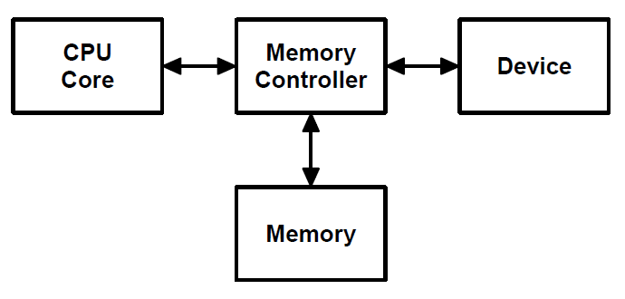
The SMMU is a hardware component that performs address translation and access control for bus initiators outside of the CPU.The bus is not directly connected to the units, it is connected to each of these unit's controller.
The DMA is not a device, but a special kind of control unit that participates in transfers to and from.
A bus transaction consists of a two-way communication between two components, during which the bus is normally unavailable for any other communication. The component that initiates a bus transaction is called the initiator, the bus master, or just the master.
The master issues a request, such as a read or write, to some other component, which is called the responder or the slave.
A transaction begins when the master issues a request and ends when the requested action has finished.
A particular bus always uses same set of rules for communication between the master and the slave. This set of rules is called the bus protocol and every device attached to the bus must follow these rules.
The bus consists of three types of wires, called lines:
- The control lines called the control bus, transmit the kind of bus transaction (e.g., READ, WRITE) and other information from the master to the slave.
- The address lines called the address bus, transmit the address of the location within the slave of the data that is to be read (read transaction) or the location into which the data is to be written (write transaction).
- The data lines called the data bus, transmit the data that is being read or written.
In addition the control bus transmits return signals from the slave to the master (e.g., MRC).
- Stage 1 usually controlled by the CPU OS, maps the virtual addresses visible to applications and the OS kernel to intermediate physical addresses visible to a virtual machine.
- Stage 2 maps intermediate physical addresses to physical addresses.
For ex., this allows a kernel driver in a virtual machine to allocate a memory buffer, provide a DMA bus initiator with its virtual address range, and rely on the SMMU to translate DMA transactions to the correct physical address ranges for the virtual machine.
Transactions targeting an address not mapped or permitted in the page tables will trigger a bus fault.
2.1. SMMU的使用模型
2.2. SMMU的硬件原理圖
2.3. StreamID
Because multiple bus initiators can forward transactions to the same SMMU concurrently, the SMMU supports multiple context banks in parallel, each with its own page tables.An SMMU directs incoming transactions to the correct context bank using signals generated by each initiator, including a stream ID and security state determination (SSD) value.
Trusted software configures the SMMU to map these transaction values to a context bank and, hence, to the corresponding page tables.
- Simple initiators have a single hard-wired stream ID and SSD value, and can be mapped to only one context bank at any time.
- More complex initiators may have internal logical channels that generate distinct stream ID and SSD values, so that each channel can be mapped to a different SMMU context bank and operate in a different security domain.
Only TrustZone can map SSD values to secure context banks, and only page tables associated with secure context banks can map virtual addresses to secure physical addresses.
2.4 STE Table 和 STE format
2.4.1 一個 Linear Stream Table的示例
2.4.2 一個 2-level Stream Table 的示例
2.4.3 Multi-level Stream and CD tables
2.4.4 Translation stages and addresses
2.4.5 Configuration and translation lookup sequence
2.5 寄存器的介紹
2.6 Stream Table Entry
2.7 Context Descriptor table
3. 總結
The Linux driver implementer's API guide :Buffer Sharing and Synchronization
The three main components of this are:
- dma-buf representing a sg_table and exposed to userspace as a file descriptor to allow passing between devices
- fence provides a mechanism to signal when one device as finished access
- reservation manages the shared or exclusive fence(s) associated with the buffer
Carveout resource management
The carveout memory is physically contiguous and set aside at boot, a memory region dedicated to coprocessor accessible by processors.On master side:
- Need to allocate requested memory region
- Need to grant CPU access to this memory region
- Need to map it on device memory domain if supported (SMMU)
- Enable memory access on defined carveout region (MPU/MMU configuration)
Common reference between master and slave is physical address.
Learn the Architecture - SMMU Software Guide
Version 1.0Overview
This guide describes the basic operation of the Arm System Memory Management Unit version 3 (SMMUv3) and use cases of the SMMUv3. It includes:- The SMMU architecture concepts, terminology and operation
- The system-level consideration relevant to what the SMMU does
- Knowledge of typical SMMU use cases
What an SMMU does
An SMMU performs a task like that of an MMU in a PE.It translates addresses for DMA requests from system I/O devices before the requests are passed into the system interconnect.
The SMMU only provides translation services for transactions from the client device, not for transactions to the client device.
Transactions from the system or PE to the client device are managed by other means, for example, the PE MMUs.

- Translation The addresses supplied by the client device are translated from the virtual address(VA) space into the system’s physical address(PA) space.
- Protection Operations from the client device might be prevented by the permissions held in the translation tables. You can prohibit a device to read, write, execute, or make any access to particular regions of memory.
- Isolation Transactions from one device can be differentiated from those of another device, even if both devices share a connection to the SMMU.
Each device might have its own private translation tables, or might share them with other devices, as appropriate to the application.

Operation of an SMMU
Translation process overview
- Global attributes, such as memory type or Shareability, might be applied from the SMMU_GBPA register of the SMMU.
- the Gconfiguration is determined
- A Stream Table Entry (STE) is located.
- If the STE enables stage 2 translation, the STE contains the stage 2 translation table base.
- If the STE enables stage 1 translation, a Context Descriptor (CD) is located. If stage 2 translation is also enabled by the STE, the CD is fetched from IPA space which uses the stage 2 translations. Otherwise, the CD is fetched from PA space.
- GTranslations are performed if the configuration is valid
- If stage 1 is configured to translate, the CD contains a stage 1 translation table base pointing to the base address of a table which is walked. If stage 1 is configured to bypass, the input address is provided directly to stage 2.
- If stage 2 is configured to translate, the STE contains a stage 2 translation table base which is used to perform the stage 2 translation. Stage 2 translates the output of stage 1, if stage 1 is enabled, or translates the input address if stage 1 is bypassed.
- the translated address with the relevant memory attributes is forwarded into the system.
Stream Security
The SMMUv3 architecture has optional support for two or three Security states.For each Security state, there are separate registers and Stream tables.
A stream can be Secure, Non-secure, or Realm, which is determined by the input signal SEC_SID.
- A Non-secure stream can only generate Non-secure downstream transactions.
- A Secure stream can generate both Secure and Non-secure downstream transactions. A Secure stream is the programming interface for a device in the Secure state.
- A Realm stream can generate both Realm and Non-secure downstream transactions.
A Secure transaction means an access to the Secure Physical Address space.
Stream identification
A system might have multiple devices sharing a single SMMU.The SMMU needs to identify different devices connected to it and to associate device traffic with translations.
The StreamID is how the SMMU distinguishes different client devices.
A device might be able to generate multiple StreamIDs, with different translations applied based on the StreamID. For example, for a DMA engine that supports multiple channels, different StreamIDs might be applied to different channels.
How the StreamID is formed is IMPLEMENTATION DEFINED.
There is a separate StreamID namespace per Security state,
- Non-secure StreamID
- Secure StreamID
- Realm StreamID
The SubstreamID, might optionally be provided to an SMMU implementing stage 1 translation. Substreams enable transactions from the same device to share the same stage 2 translation, but have different stage 1 translations.
When a SubstreamID is supplied with a transaction and the configuration enables substreams, the SubstreamID indexes the CD table to select a stage 1 translation context.
Fault model
The flow how an SMMU records and reports a fault.
- If a transaction type or property is unsupported by an SMMU for IMPLEMENTATION DEFINED reasons, an Unsupported Upstream Transaction fault (F_UUT) event is recorded and the transaction is terminated with an abort.
- The StreamID and SubstreamID, if supplied, are used to locate a configuration for the transaction. If any of the required STE and CD cannot be located or are invalid, a configuration error event is recorded, and the transaction is terminated with an abort.
- If a valid configuration is located so that the translation tables can be accessed, the translation process begins. Other faults can occur during this phase. Translation-related faults and fault types:
- F_TRANSLATION Translation fault
- F_ADDR_SIZE Address Size fault
- F_ACCESS Access Flag fault
- F_PERMISSION Permission fault
Bypass
Address Translation Services
Page Request Interface
Programming the SMMU
SMMU registers
Stream table
CD
Event queue
A set of configuration errors and faults are recorded in the Event queue if they occur.
- There is one Event queue per Security state.
- The SMMU generates an interrupt when the Event queue transitions from empty to non-empty.
- for the Command queue, the SMMU is the consumer
- for the Event queue, the SMMU is the producer
The system software is expected to consume entries from the Event queue quickly to avoid overflow during normal operation.
Event records are 32 bytes in size. For a complete description of Event records, see Arm System Memory Management Unit version 3
Command queue
Arm System Memory Management Unit Architecture Specification
SMMU architecture version 3Chapter 2 Introduction
A System Memory Management Unit (SMMU) performs a task translating addresses for DMA requests from system I/O devices before the requests are passed into the system interconnect.Traffic in the other direction, from the system or PE to the device, is managed by other means – for example, the PE MMUs.

An SMMU might translate traffic from just one device or a set of devices.
Translation of DMA addresses might be performed for reasons of isolation or convenience.
In order to associate device traffic with translations and to differentiate different devices behind an SMMU, requests need an extra property to identify a stream.
Different streams are logically associated with different devices and the SMMU can perform different translations or checks for each stream.
The SMMU supports two stages of translation:
- An incoming address is logically translated from VA to IPA in stage 1 Stage 1 is intended to be used by a software entity to provide isolation or translation to buffers within the entity, for example DMA isolation within an OS.
- the IPA is input to stage 2 which translates the IPA to the output PA Stage 2 is intended to be available in systems supporting the Virtualization Extensions and is intended to virtualize device DMA to guest VM address spaces
When both stage 1 and stage 2 are enabled, the translation configuration is called nested.
The SMMU programming interface register SMMU_AIDR indicates which SMMU architecture version the SMMU implements .
2.7 System placement

Chapter 3 Operation
3.1 Software interface
The SMMU has three interfaces that software uses:- Memory-based data structures to map devices to translation tables which are used to translate client device addresses.
- Memory-based circular buffer queues.
- A set of registers
3.2 Stream numbering
The mapping of a physical device to StreamID must be described to system software.The StreamID namespace is per-SMMU.
Devices assigned the same StreamID but behind different SMMUs are seen to be different sources.
A device might emit traffic with more than one StreamID, representing data streams differentiated by device-specific state.
StreamID is of IMPLEMENTATION DEFINED size, between 0 and 32 bits.
The StreamID is used to select a Stream Table Entry (STE) in a Stream table, which contains per-device configuration.
3.3 Data structures and translation procedure
The SMMU uses a set of data structures in memory to locate translation data:- Registers hold the base addresses of the initial root structure, the Stream Table. A Stream table entry (STE) contains stage 2 translation table base pointers, and also locates stage 1 configuration structures, which contain translation table base pointers.
- A Context descriptor (CD) represents stage 1 translation, The first step in dealing with an incoming transaction is to locate the STE, identified by its StreamID and, optionally, SubstreamID,
Translation table structures that are used to perform the VA to IPA and IPA to PA translation of addresses

留言