ARM TF + OPTEE
不知是否為了與 ARM 公司名稱縮寫吻合, ARM 旗下 CPU IP 三大產品線簡稱也正好是 ARM ,分別是 Cortex-A 、 Cortex-R 以及 Cortex-M ,三者雖同為 CPU 架構,但所具備的機能卻有明顯的差異化, Cortex-A 是針對運算級應用並可執行完整的 OS ,而同樣執行 RTOS 的 Cortex-R 與 Cortex-M 則是各別針對需要及時反應以及省電小體積的需求。
- A The Application profile defines an architecture aimed at high performance processors, supporting a virtual memory system using a Memory Management Unit (MMU) and therefore capable of running fully featured operating systems.
- R The Real-time profile defines an architecture aimed at systems that require deterministic timing and low interrupt latency. There is no support for a virtual memory system, but memory regions can be protected using a simple Memory Protection Unit (MPU).
- M The Microcontroller profile defines an architecture aimed at low cost systems, where low-latency interrupt processing is vital.
Support for the ARM and Thumb instruction sets is provided.
ARMv7-A, the Application profile, is implemented by all Cortex-A series processors, and by processors developed by companies who have licensed the ARM architecture.
The ARMv8-A architecture, which is not described in this book, supports the AArch32 state, a 32-bit implementation of the architecture that is backwards compatible with ARMv7-A.
Cortex-R 的應用領域是需要能及時反應操作動作,例如馬達速度管理、車載的引擎控制管理,能用於像是機械手臂,汽車的電子化油門、引擎控制,電動車的電力管控等等,近年更用於高流量網通晶片解決大數據量及時處理
It uses a different exception handling model to the other profiles and supports only a variant of the Thumb instruction set.
重視省電與縮小晶片體積,常見於感測器管理、數據機等應用。
ARM Processor Modes and Registers
The ARM architecture is a modal architecture.There are privileged modes and a non-privileged user mode.
Privilege is the ability to perform certain tasks that cannot be done from User (Unprivileged) mode. For example, MMU configuration and cache operations.
Modes are associated with exception events.
The introduction of the TrustZone Security Extensions:
- created two security states for the processor
- modes existing independently for each security state
- a new Monitor mode to act as a gateway between the Secure and Non-secure states

The ARMv7-A architecture Virtualization Extensions add a Hypervisor mode (Hyp), virtualization enables more than one Operating System to co-exist and operate on the same system.

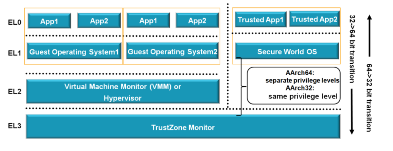
在Priviledge Level上,armv8提出了新的EL的概念。
Exception levels
The name for privilege in AArch64 is Exception level, often abbreviated to EL.The Exception levels are numbered, normally abbreviated and referred to as EL<x>, where <x> is a number between 0 and 3.
The higher the level of privilege the higher the number. For example, the lowest level of privilege is referred to as EL0.
The architecture does not specify what software uses which Exception level.
A common usage model is application code running at EL0, with a rich Operating System (OS) such as Linux running at EL1. EL2 may be used by a hypervisor, with EL3 used by firmware and security gateway code.
Therefore, these Privilege Levels are referred to as Exception Levels in the Arm architecture.

- Taking an exception When taking an exception the Exception level can increase or stay the same. You can never move to a lower privilege level by taking an exception.
- Returning from an exception When returning from an exception the Exception level can decrease or stay the same. You can never move to a higher privilege level by returning from an exception.
- Processor reset
- During Debug state
- Exiting from Debug state

An exception is any condition that requires the core to halt normal execution and instead execute a dedicated software routine known as an exception handler associated with each exception type.
Other architectures might refer to what ARM calls exceptions as traps or interrupts, however, in the ARM architecture, these terms are reserved for specific types of exceptions.
The Arm architecture categorizes exceptions into two broad types: synchronous exceptions and asynchronous exceptions.
- Synchronous exceptions are exceptions that can be caused by, or related to, the instruction that has just been executed.
- Some types of exceptions(interrupts) are generated externally, and therefore are not synchronous with the current instruction stream.
Types of privilege
There are two types of privilege relevant to the AArch64 Exception model:- Privilege in the memory system
- Privilege from the point of view of accessing processor resources
Memory privilege
The A-profile of the Arm architecture implements a virtual memory system, in which a Memory Management Unit (MMU) allows software to assign attributes to regions of memory.These attributes include read/write permissions that can be configured to allow separate access permissions for privileged and unprivileged accesses.
- Memory access initiated when the processor is executing in EL0 are checked against the unprivileged access permissions.
- Memory accesses from EL1, EL2, and EL3 are checked against the privileged access permissions.
The MMU configuration is stored in System registers, and the ability to access those registers is also controlled by the current Exception level.
Configuration settings for AArch64 processors are held in a series of registers known as System registers.
For example, VBAR_EL1 is the Vector Base Address Register, the _EL1 suffix tells us that software needs at least EL1 privilege to access the register.
The combination of settings in the System registers defines the current processor context.
The registers have similar names to reflect that they perform similar tasks, but they are entirely independent registers with their own access semantics. The suffix of the System register name indicates the lowest Exception level from which that register can be accessed.
There is a System Control Register (SCTLR) for each implemented Exception level. Each register controls the architectural features for that EL, such as the MMU, caches and alignment checking:
- SCTLR_EL1 Top-level system control for EL0 and EL1.
- SCTLR_EL2 Top-level system control for EL2
- SCTLR_EL3 Top-level system control for EL3
There is no SCTLR_EL0 and all control is from the EL1 accessible register.
This model is generally followed for other control registers.
Execution and Security states
The current state of an Armv8-A or Armv9-A processor is determined by the Exception level and the current Execution state.- The AArch64 architecture provides 4 Exception Levels.
- There are also 2 Execution States and up to 4 Security States.
Execution states
Armv8-A and Armv9-A support two Execution states:- AArch32 AArch32 is a 32-bit Execution state.
- AArch64 AArch64 is a 64-bit Execution state.
Operation in this state is backward compatible with previous architectures.
It supports the T32 and A32 instruction sets. The standard register width is 32 bits.
It supports the A64 instruction set. The standard register width is 64 bits.
The Execution state also affects aspects of the memory models and how exceptions are managed.
A Processing Element (PE) can only change Execution state on reset or when the Exception level changes.
The transitioning between AArch32 and AArch64 is only allowed subject to additional rules:
- When moving from a lower Exception level to a higher level, the Execution state can stay the same or change to AArch64.
- When moving from a higher Exception level to a lower level, the Execution state can stay the same or change to AArch32.

This utilizes:
- the Hypervisor Configuration Register (HCR_EL2) at EL2
- the Secure Configuration Register (SCR_EL3) at EL3
Security states
Most Cortex-A processors support 2 Security states:- Secure state In this state, a Processing Element (PE) can access both the Secure and Non-secure physical address spaces, and the Secure copy of banked registers.
- Non-secure state This is often also referred to as Normal world.
- can only access the Non-secure physical address space
- can only access System registers that allow non-secure accesses
In this state, a PE

If TrustZone is implemented then the processor can be in either Secure state or Non-secure state. This is selected by the SCR_EL3.NS bit.
EL3 is the most privileged Exception level and the Security state of EL3 is fixed.
EL3 is able to access all copies of a banked System register.
Whenever you want to switch from one Security state to another you must pass through EL3. Software at EL3 is responsible for managing access to the different available Security states and acts as a gatekeeper, controlling access to the Security states of EL2, EL1 and EL0.
The SCR_EL3.NS bit enables a change of Security state on return from EL3.
Changing Security state is discussed in more detail in TrustZone for AArch64 and Realm Management Extension.
Impact of implemented Exception levels
It is an implementation choice for any specific processor:- whether all Exception levels are implemented
- which Execution states are allowed for each implemented Exception level
EL2 and EL3 are optional:
- EL2 contains much of the virtualization functionality. Implementations that do not have EL2 do not have access to these features. For more on virtualization see the AArch64 virtualization guide.
- EL3 is the only level that can change Security state. If an implementation chooses not to implement EL3, that PE would only have access to a single Security state. The state you are permanently in is therefore IMPLEMENTATION DEFINED.
Exception types
An exception is any event that can cause the currently executing program to be suspended.Taking an exception causes a change in state to execute code to handle that exception.

Exceptions are used for many different reasons, including the following:
- Emulating virtual devices
- Virtual memory management
- Handling software errors
- Handling hardware errors
- Debugging
- Performing calls to different privilege or security states
- Handling interrupts (timers, device interactions)
- Handling across different Execution states (known as interprocessing)
Synchronous exceptions
Synchronous exceptions are synchronous to the execution stream, as they are directly related to the currently executing instruction.For example a synchronous exception would be triggered by an instruction attempting to write to a read-only location as defined by the MMU.
Exception-generating instructions
There are instructions that intentionally cause an exception to be generated and taken.These instructions are used to implement system call interfaces to allow less privileged software to request services from more privileged software. These are sometimes called system calls and are often used in software-based APIs.
The Arm architecture includes the exception-generating instructions:
- The Supervisor Call (SVC) instruction enables a user program at EL0 to request an OS service at EL1
- The Hypervisor Call (HVC) instruction enables the OS to request hypervisor services at EL2
- The Secure Monitor Call (SMC) instruction enables the Normal world to request Secure world services from firmware at EL3

Asynchronous exceptions
Some types of exceptions are generated externally and therefore are not synchronous with the current instruction stream.Asynchronous exceptions are also known as interrupts. We do not know when they will occur.
- Physical interrupts Physical interrupts are those generated in response to a signal from outside the PE, typically by peripherals.
- SError System Error (SError) is an exception type that is intended to be generated by the memory system in response to unexpected events.
- IRQ and FIQ IRQ and FIQ have independent routing controls and are often used to implement Secure and Non-secure interrupts, as discussed in the Arm Generic Interrupt Controller v3 and v4 guide.
- Virtual interrupts The interrupts seen by the VM are virtual interrupts. Virtual interrupts can be externally generated by a device connected to an interrupt controller or may be generated by software.
- vSError(Virtual System Error)
- vIRQ(Virtual IRQ)
- vFIQ(Virtual FIQ)
All Arm implementations use the Arm Generic Interrupt Controller (GIC) architecture for the management of IRQs and FIQs. The GIC performs the tasks of interrupt management, prioritization, and routing, providing a single signal per physical interrupt type into the core.
Virtual interrupts can be generated either from a hypervisor at EL2 or by using an interrupt controller. The hypervisor must set the corresponding routing bit in the Hypervisor Configuration Register (HCR_EL2).
Handling exceptions
- The state that the processor is in when the exception is recognized is known as the state the exception is taken from.
- The state the PE is in immediately after the exception is the state the exception is taken to.
After an exception has been handled, the system needs to return from the state it has been taken to.
This is known as an Exception return, and the Arm architecture has instructions that trigger an Exception return.
Taking an exception
When an exception occurs, the processor- saves the current status of the PE alongside the exception return address A snapshot of current state is taken from PSTATE and written to the Saved Program Status Register (SPSR).
- enters a specific mode to handle the exception When an exception is taken to an ELx,
- The contents of PSTATE immediately before the exception was taken is written to SPSR_ELx.
- The preferred exception return address is written to ELR_ELx.
- For synchronous exceptions and SError interrupts, exception syndrome information (the cause of the exception) is written to ESR_ELx.
- For address-related synchronous exceptions, such as MMU faults, the virtual address that triggered the exception is written to the Fault Address Register, FAR_ELx.
- On taking an exception, the EL can stay the same or increase.
- On an exception return, the EL can stay the same or decrease.
- the only way to gain privilege is by taking an exception
- the only way to lose or reduce privilege is by performing an exception return
The return address is written to an Exception Link Register (ELR).
For synchronous exceptions and SErrors another register, the Exception Syndrome Register (ESR), is also updated. This records the cause of the exception.
When an exception occurs the Processing Element (PE) branches to a location in a vector table.
The vector table location is normally configured to contain the handler code(Top-level handler) to perform generic actions and to branch to further exception handling code according to the exception type.

Each exception type targets an Exception level (EL) to which an exception is taken. This means:
The interaction between AArch32 and AArch64 Execution states is called interprocessing.
AArch32 general-purpose registers are directly mapped to the AArch64 registers to allow AArch64 handler code to access AArch32 registers.
PSTATE is this information that is stored in the SPSR.
Each exception type has a target Exception level that is either:
- Implicit according to the type of the exception fixed by the architecture
- Defined by configuration bits in the System registers configured by software using routing controls
Other classes of exception can be routed to EL2 (Hypervisor) or EL3 (Secure Monitor).
Routing is set independently for IRQs, FIQs, and SErrors.
Routing is configured using the Secure Configuration Register SCR_EL3 and the Hypervisor Configuration Register HCR_EL2.
These allow different interrupt types to be routed to different Exception levels.
For example, IRQs might be handled by the OS at EL1 whereas SErrors would more typically be handled by the firmware running at EL3.
The routing bits in these registers have an UNKNOWN value at reset, so they must be initialized by software.
It is common for the Arm Generic Interrupt Controller (GIC) architecture to be used to perform the task of interrupt management, prioritization, and routing.
- Exceptions routed to a higher Exception level cannot be masked by the lower EL.
- Exceptions routed to the current Exception level can be masked by the current level.
Vector tables are an area of normal memory containing instructions that are then used to handle the exception.
The location in memory where the handler is stored is called the exception vector.
Each Exception level has its own vector table, with the base address defined by its own Vector Base Address Register, VBAR_EL<x>, where <x> is 1,2, or 3.
Returning from an exception
The handler returns to the code that was running before the exception happened.It does this by :
- Restoring all previously stacked corruptible registers
- Initiating an exception return instruction (ERET) The ERET instruction restores the previous processor state from the associated SPSR and branches to the exception return address recorded in the ELR.
On execution of the ERET instruction, PSTATE is restored from SPSR_ELx, and the program counter is updated to the value in ELR_ELx.
Understanding ARM Trusted Firmware using QEMU
“ARM Trusted Firmware is a Reference implementation of secure world software for ARMv8-A, including Exception Level 3 (EL3) software.”
The source files for ATF are available in github.
The components part of the ATF are BL1, BL2 and BL31.
For AArch64, a typical system will consist of five components:
- Boot Loader stage 1 (BL1) AP Trusted ROM
- Boot Loader stage 2 (BL2) Trusted Boot Firmware
- Boot Loader stage 3-1 (BL31) EL3 Runtime Software
- Boot Loader stage 3-2 (BL32) Secure-EL1 Payload (optional)
- Boot Loader stage 3-3 (BL33) Non-trusted Firmware

Trusted Firmware Design
Trusted Firmware-A (TF-A) implements a subset of the Trusted Board Boot Requirements (TBBR) Platform Design Document (PDD) for Arm reference platforms:- TF-A also implements the PSCI as a runtime service PSCI is the interface from normal world software to firmware implementing power management use-cases (for example, secondary CPU boot, hotplug and idle).
- Normal world software can access TF-A runtime services via the Arm SMC (Secure Monitor Call) instruction. The SMC instruction must be used as mandated by the SMC Calling Convention (SMCCC).
- TF-A implements a framework for configuring and managing interrupts generated in either security state. The details of the interrupt management framework and its design can be found in `Interrupt Management Framework`.
- TF-A also implements a library for setting up and managing the translation tables. The details of this library can be found in `Translation (XLAT) Tables Library`.
- TF-A can be built to support either AArch64 or AArch32 execution state.
Cold boot
The cold boot path starts when the platform is physically turned on.- one of the CPUs released from reset is chosen as the primary CPU, and the remaining CPUs are considered secondary CPUs.
- The primary CPU is chosen through platform-specific means. The cold boot path is mainly executed by the primary CPU.
- The secondary CPUs are kept in a safe platform-specific state until the primary CPU has performed enough initialization to boot them.
- Regions accessible from both non-secure and secure states. For example, non-trusted SRAM, ROM and DRAM.
- Regions accessible from only the secure state. For example, trusted SRAM and ROM.
The FVPs also implement the trusted DRAM which is statically configured.
Additionally, the Base FVPs and Juno development platform configure the TrustZone Controller (TZC) to create a region in the DRAM which is accessible only from the secure state.
Dynamic Configuration during cold boot
Each of the Boot Loader stages may be dynamically configured if required by the platform.
Each Boot Loader stage can pass up to 4 arguments via registers to the next stage.
- BL2 passes the list of the next images to execute to the EL3 Runtime Software (BL31 for AArch64 and BL32 for AArch32) via arg0.
- All the other arguments are platform defined.
- FW_CONFIG - The firmware configuration file. Holds properties shared across all BLx images. An example is the "dtb-registry" node, which contains the information about the other device tree configurations (load-address, size, image_id).
- HW_CONFIG - The hardware configuration file. Can be shared by all Boot Loader stages and also by the Normal World Rich OS.
- TB_FW_CONFIG - Trusted Boot Firmware configuration file. Shared between BL1 and BL2.
- SOC_FW_CONFIG - SoC Firmware configuration file. Used by BL31.
- TOS_FW_CONFIG - Trusted OS Firmware configuration file. Used by Trusted OS (BL32).
- NT_FW_CONFIG - Non Trusted Firmware configuration file. Used by Non-trusted firmware (BL33).
- BL1 passes the address of a meminfo_t structure to BL2 via arg1. This structure contains the memory layout available to BL2.
- When dynamic configuration files are present, the firmware configuration for the next Boot Loader stage is populated in the first available argument and the generic hardware configuration is passed the next available argument. For ex.,
- For the BL2 image FW_CONFIG is loaded by BL1, then its address is passed in arg0 to BL2.
- For the BL31 image SOC_FW_CONFIG is loaded by BL2, then its address is passed in arg1 to BL31. (Note, arg0 is used to pass the list of executable images.)
- For other BL3x images If the firmware configuration file is loaded by BL2, then its address is passed in arg0 and if HW_CONFIG is loaded then its address is passed in arg1.
HW_CONFIG is loaded by BL1, then its address is passed in arg2 to BL2. (Note, arg1 is already used for meminfo_t.)
HW_CONFIG is loaded by BL1 or BL2, then its address is passed in arg2 to BL31.
BL1
BL2
AArch64 BL31 (Secure Monitor Firmware)
- The BL31 image is loaded by BL2
- BL1 passes control to BL31 at EL3
The functionality implemented by BL31 is as follows:
- Architectural initialization
- Platform initialization
- Runtime services initialization
- AArch64 BL32 (Secure-EL1 Payload, Trusted OS) image initialization
- BL33 (Non-trusted Firmware) execution
EL3 runtime services framework
Software executing in the non-secure state and in the secure state at exception levels lower than EL3 will request runtime services using the Secure Monitor Call (SMC) instruction.The SMCCC(SMC Calling Convention) assigns function identifiers to each SMC request and describes how arguments are passed and returned.
Secure-EL1 Payloads and Dispatchers
TF-A uses a more general term for the BL32 software that runs at Secure-EL1 - the Secure-EL1 Payload - as it is not always a Trusted OS.
Exception handling in BL31
Memory layout of BL images
An Introduction to ARM Trusted Firmware
- V6: OS running on the SOC
- V7: OS running on the Hypervisor/SOC
- V7: Secure World
- V8: A Profile `


The processor maintais the secure and non-secure states by 2 set of registers.


Technical Overview of the Trusted Firmware: A Class Open Source Project
- The communications between the Normal World and the Secure World relys on the SMC
- TF-A
- BL31 is the Secure Monitor
- Trusted Boot Based on:
- Immutable root-of-trust(ROT) publick key
- Immutable secure boot ROM firmware
- Each firmware stage verifies the signature of the next one From BL1(ROM firmware) up to BL33(the normal worlld boot loader)
- TrustedFirmware without a Trusted OS
- TrustedFirmware with a Trusted OS


Trusted Firmware
Trusted Firmware-A (TF-A) is a reference implementation of secure world software for Arm A-Profile architectures (Armv8-A and Armv7-A), including an Exception Level 3 (EL3) Secure Monitor.It provides a suitable starting point for productization of secure world boot and runtime firmware, in either the AArch32 or AArch64 execution states.
TF-M is being built for Arm Cortex-M processors prioritizing v8-M Cortex cores leveraging Arm TrustZone technology.

- Power State Coordination Interface (PSCI)
- Trusted Board Boot Requirements CLIENT (TBBR-CLIENT)
- SMC Calling Convention
- System Control and Management Interface (SCMI)
- Software Delegated Exception Interface (SDEI)
Development of TEE and Secure Monitor Code

This requires a simple solution comprising of a lightweight secure kernel and integration of the monitor for switching between normal and secure domains.
Arm recommends investigating commercial TEE solutions for the Secure OS.
Arm Architectural Reference Manuals
To assist in the development of a Trusted Execution Environment, utilization of Secure Monitor capability, or review of a third-party TEE, Arm suggests that partners review the documentation listed below:- Armv6 & Armv7-AR Architecture
- Armv8-A Instruction Set Architecture
- Armv8-A Reference Manual The Arm Architecture Reference Manuals define the implementation and instructions utilized in the TrustZone SMC plus variations within the exception model between v7 and v8 of the architecture.
Secure Boot
Secure boot is a mechanism that guarantees only the trusted firmware is executed:- the digital signature This is used to identify whether the loaded firmware is secured or corrupted
- the private key This is used to generate the correct digital signature
- the public key This is on the device and protected by hardware, such as OTP (One-Time Programmable).
- Secure Boot by Secure Storage
- the Boot ROM is not secured
- both BST and BLD are physically protected by secure storage Secure NAND or eMMC with permanent lock capability.
- The public key/certificate is appended to the BLD on the secure storage.
- Secure Boot by Built-in HW Engine
- the Boot ROM is secured This provided RSA and SHA functions (called Built-in HW engine) to verify other firmwares.
- The public key/certificate is stored on the OTP.
- BST and BLD are appended with a signature signed by the private key
- Secure ROM authenticates BST(Bootstrap) Boot Loader stage 1 (BL1) AP Trusted ROM.
- BL1 loads a BL2 raw binary image from platform storage
- BL1 passes control to the BL2 image at Secure EL1 (for AArch64) or at Secure SVC mode (for AArch32), starting from its load address.
- BST reuses the (RSA/SHA) code block inside the Secure ROM and authenticates ATF (BL2)
- BL2 authenticates BL31, BL32, and BL33. Boot Loader stage 2 (BL2) Trusted Boot Firmware.
- BL31 EL3 Runtime (Monitor) firmware.
- BL32 Secure-EL1 Payload (optional).
- BL33 Non-trusted Firmware.
- BL33 authenticates the Linux Kernel.
BL1 code starts execution from the reset vector defined by the constant BL1_RO_BASE.
The BL1 data section is copied to the top of trusted SRAM as defined by the constant BL1_RW_BASE.
BL2 performs the minimal architectural initialization required for subsequent stages of TF-A and normal world software.
BL2 generic code loads the images based on the list of loadable images provided by the platform.
Firmware Image Package (FIP) is a packaging format used by TF-A to package firmware images in a single binary.
The FIP layout consists of a table of contents (ToC) followed by payload data.
------------------
| ToC Header     |
|----------------|
| ToC Entry 0    |
|----------------|
| ToC Entry 1    |
|----------------|
| ToC End Marker |
|----------------|
|                |
|     Data 0     |
|                |
|----------------|
|                |
|     Data 1     |
|                |
------------------
For example, most platforms require a BL33 image which corresponds to the normal world bootloader (e.g. UEFI or U-Boot).The TF-A build system provides the make target fip to create a FIP file for the specified platform using the FIP creation tool "fiptool".
BL2 passes control back to BL1 by raising an SMC, providing BL1 with the BL31 entrypoint.
The exception is handled by the SMC exception handler installed by BL1. BL1 passes control to BL31 at the specified entrypoint at EL3.
BL32 (a Trusted OS) is an optional module for the system.
If the user does not need Arm TrustZone®, BL32 can be removed.
BL2 loads the BL33 image (e.g. UEFI or other test or normal boot loader) from platform storage into non-secure memory as defined by the platform.
Partitions
+----------------------------------------------------------+
| BST                                                      |
+----------------------------------------------------------+
| ATF(BL2)                                                 |
+----------------------+-----------------------------------+
|                      | BL31 (the secure monitor for ATF) |
|                      +-----------------------------------+
|  BLD                 | BL32 (trusted OS: OPTEE-OS)       |
|                      +-----------------------------------+
|(Firmware in package) | BL33 (real BLD)                   |
+----------------------+-----------------------------------+
|  Linux   kernel                                          |
+----------------------------------------------------------+
|  Linux   rootfs                                          |
+----------------------------------------------------------+
| partition table                                          |
+----------------------------------------------------------+
Signed by ROT key:
- BST
- ATF
Chain of Trust Defined by ATF
ATF defines the CoT (Chain of Trust), which describes the ROT key and its derived keys.The root of trust is usually a public key (ROTPK) that has been burnt in the platform and cannot be modified.
Images in a CoT are categorised as:
- authentication image An authentication image contains information to authenticate a data image or another authentication image.
- data image A data image is usually a boot loader binary, but it could be any other data that requires authentication.
If the image is an authentication image, extract the information that will be used to authenticate the next image in the CoT.
Key Management
Public Keys on the Device
The public keys are deployed on the device.- The ROT public key (ROTPK) gets programmed into OTP. amboot/build/keys/rot_private.pem
- the TA public key is embedded into the OPTEE-OS binary optee-os/src/keys/default_ta.pem
- The public key for authenticating the Linux kernel is embedded into the real boot loader binary.
Private keys must be kept confidential
As private keys are required for compiling firmware, in the default approach, they are located in the ATF/OPTEE source code directory.
The RPC toolkit is used to prevent the high risk of private key leakage.
- The developer install the remote server public key
- The remote server has installed the developer's certificate
- Makefile can request a signing service via tool proxies, which connects the daemon. The daemon running on the developer side requests the signing service over a TLS connection with the remote server.
Prepare the Key Pairs
Example
The certificate and private key are manually downloaded then put into to the sorce folder before bilding the code.Arm® Platform Security Architecture Trusted Boot and Firmware Update
A Trusted Boot process involves verifying and measuring software in accordance to a chain of trust.- Secure boot At each stage of the boot process, check that code is authorized to run before execution.
- Measured boot Cryptographically measuring the code and critical data so that the security state can be attested to later.
Since this occurs recursively it creates a “chain of trust”.
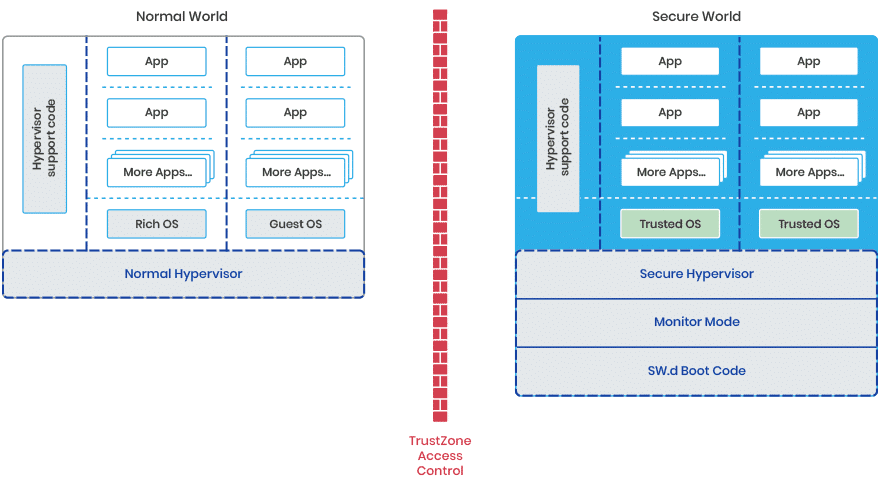
TEE and Arm TrustZone
TEE stands for Trusted Execution Environment. It is a specification/standard from Global Platform (GP), which is a non-profit industry association.Arm TrustZone is one of the TEE implementations.
Arm Trusted Firmware
Arm Trusted Firmware (ATF) is the reference software for Arm TrustZone.It implements a secure monitor, which handles the switch between the normal world (rich OS) and the secure world (secure OS).
ATF also implements authentication during the boot stage (secure boot): BL2 authenticates BL31, BL32, and BL33.
The CoT relies on a public key infrastructure generating self-signed certificate.
There is no Certificate Authority (CA) because the CoT is not established by verifying the validity of a certificate's issuer.
Different keys are used for this CoT:
- Root of trust key The private part of this key is used to sign the BL2 content certificate and the trusted key certificate.
- Trusted world key The private part is used to sign the key certificates corresponding to the secure world images (SCP_BL2, BL31 and BL32).
- Non-trusted world key The private part is used to sign the key certificate corresponding to the non secure world image (BL33).
- BL3X content keys For each of SCP_BL2, BL31, BL32 and BL33, the private part is used to sign the content certificate for the BL3X image.
The public part is the ROTPK.
The public part is stored in one of the extension fields in the trusted key certificate.
The public part is stored in one of the extension fields in the trusted key certificate.
The public part is stored in one of the extension fields in the corresponding key certificate.
It contains the public part of the trusted world key and the public part of the non-trusted world key.
Building Documentation
$ sudo apt install python3 python3-pip plantuml
$ cd arm-trusted-firmware/docs
$ pip3 install -r requirements.txt
$ make html
The build HTML documents are under:
./build/html
Prerequisites
$ sudo apt install build-essential git libssl-dev
$ sudo apt install device-tree-compiler
Source code for TF-A is maintained in a Git repository hosted on TrustedFirmware.org.
git clone "https://review.trustedfirmware.org/TF-A/trusted-firmware-a"
Building Supporting Tools
Building and using the FIP tool
FIP is a packaging format used by TF-A to package firmware images in a single binary.
It can contains:
- Boot stage binaries
- Configuration file (Device tree)
- Certificate (X509.3 based) for authentication
For example, most platforms require a BL33 image which corresponds to the normal world bootloader (e.g. UEFI or U-Boot).
The TF-A build system provides the make target fip to create a FIP file for the specified platform using the FIP creation tool included in the TF-A project.
Examples below show how to build a FIP file for FVP, packaging TF-A and BL33 images:
- AArch64
$ make PLAT=fvp BL33=path-to/bl33.bin fip
$ make PLAT=fvp ARCH=aarch32 AARCH32_SP=sp_min BL33=path-to/bl33.bin fip
The resulting FIP may be found in:
build/fvp/build-type/fip.binIt is also possible to independently build the fip tool:
$ make -C tools/fiptool clean
$ make [DEBUG=1] [V=1] fiptool
The built binary can be located in:
./tools/fiptool/fiptoolUsage:
- create a new Firmware package fip.bin that contains BL2 and BL31
./tools/fiptool/fiptool create \
    --tb-fw build/platform/build-type/bl2.bin \
    --soc-fw build/platform/build-type/bl31.bin \
    fip.bin
./tools/fiptool/fiptool info path-to/fip.bin
./tools/fiptool/fiptool update \
    --tb-fw build/platform/release/bl2.bin \
    build/platform/debug/fip.bin
./tools/fiptool/fiptool unpack path-to/fip.bin
./tools/fiptool/fiptool remove \
    --tb-fw build/platform/debug/fip.bin
Building the Certificate Generation Tool: cert_create
When the TRUSTED_BOARD_BOOT feature is enabled, the FIP must contain the binaries and their associated certificate as described in the TBBR(Trusted Board Boot Requirement) Chain of Trust (CoT).These certificates can be created using the cert_create command that is provided in the TF-A sources tools/cert_create.
The cert_create tool is built as part of the TF-A build process when the fip make target is specified and TBB(Trusted Board Boot) is enabled.
It can also be built separately with the following command:
$ make PLAT=platform [DEBUG=1] [V=1] certtoolThe following command should be used to obtain help about the tool:
$ ./tools/cert_create/cert_create -h
The certificate generation tool loads the binary images and
optionally the RSA keys, and outputs the key and content
certificates properly signed to implement the chain of trust.
If keys are provided, they must be in PEM format.
Certificates are generated in DER format.

Usage:
	./tools/cert_create/cert_create [OPTIONS]

Available options:
	-h,--help                        Print this message and exit
	-a,--key-alg <arg>               Key algorithm: 'rsa' (default)- RSAPSS scheme as per PKCS#1 v2.1, 'ecdsa'
	-b,--key-size <arg>              Key size (for supported algorithms).
	-s,--hash-alg <arg>              Hash algorithm : 'sha256' (default), 'sha384', 'sha512'
	-k,--save-keys                   Save key pairs into files. Filenames must be provided
	-n,--new-keys                    Generate new key pairs if no key files are provided
	-p,--print-cert                  Print the certificates in the standard output
	--tb-fw-cert <arg>               Trusted Boot FW Certificate (output file)
	--trusted-key-cert <arg>         Trusted Key Certificate (output file)
	--scp-fw-key-cert <arg>          SCP Firmware Key Certificate (output file)
	--scp-fw-cert <arg>              SCP Firmware Content Certificate (output file)
	--soc-fw-key-cert <arg>          SoC Firmware Key Certificate (output file)
	--soc-fw-cert <arg>              SoC Firmware Content Certificate (output file)
	--tos-fw-key-cert <arg>          Trusted OS Firmware Key Certificate (output file)
	--tos-fw-cert <arg>              Trusted OS Firmware Content Certificate (output file)
	--nt-fw-key-cert <arg>           Non-Trusted Firmware Key Certificate (output file)
	--nt-fw-cert <arg>               Non-Trusted Firmware Content Certificate (output file)
	--fwu-cert <arg>                 Firmware Update Certificate (output file)
	--rot-key <arg>                  Root Of Trust key (input/output file)
	--trusted-world-key <arg>        Trusted World key (input/output file)
	--non-trusted-world-key <arg>    Non Trusted World key (input/output file)
	--scp-fw-key <arg>               SCP Firmware Content Certificate key (input/output file)
	--soc-fw-key <arg>               SoC Firmware Content Certificate key (input/output file)
	--tos-fw-key <arg>               Trusted OS Firmware Content Certificate key (input/output file)
	--nt-fw-key <arg>                Non Trusted Firmware Content Certificate key (input/output file)
	--tfw-nvctr <arg>                Trusted Firmware Non-Volatile counter value
	--ntfw-nvctr <arg>               Non-Trusted Firmware Non-Volatile counter value
	--tb-fw <arg>                    Trusted Boot Firmware image file
	--tb-fw-config <arg>             Trusted Boot Firmware Config file
	--hw-config <arg>                HW Config file
	--scp-fw <arg>                   SCP Firmware image file
	--soc-fw <arg>                   SoC AP Firmware image file(BL31)
	--soc-fw-config <arg>            SoC Firmware Config file
	--tos-fw <arg>                   Trusted OS image file(BL32)
	--tos-fw-extra1 <arg>            Trusted OS Extra1 image file
	--tos-fw-extra2 <arg>            Trusted OS Extra2 image file
	--tos-fw-config <arg>            Trusted OS Firmware Config file
	--nt-fw <arg>                    Non-Trusted World Bootloader image file(BL33)
	--nt-fw-config <arg>             Non Trusted OS Firmware Config file
	--scp-fwu-cfg <arg>              SCP Firmware Update Config image file
	--ap-fwu-cfg <arg>               AP Firmware Update Config image file
	--fwu <arg>                      Firmware Updater image file
- input files
- generated files
| fiptool option | Makefile variable | Description | file path |
|---|---|---|---|
| --soc-fw | BL31 | EL3 Runtime Firmware | bl31.bin |
| --soc-fw-config | SoC Firmware Config file | board.dtb | |
| --tos-fw | BL32 | Secure OS (OP-TEE) | tee-pager_v2.bin |
| --tos-fw-extra1 | BL32_EXTRA1 | OP-TEE pager | |
| --tos-fw-extra2 | BL32_EXTRA2 | OPTEE pageable | |
| --fw-config | FW_CONFIG | Firmware configuration file | |
| --hw-config | BL33_CFG | Bootloder device tree | |
| --nt-fw | BL33 | Non-Trusted World Bootloader | bld_release.bin |
| fiptool option | Makefile variable | Description | file path |
|---|---|---|---|
| --trusted-key-cert | Trusted Key Certificate | trusted_key.crt | |
| --soc-fw-key-cert | SoC Firmware Key Certificate | soc_fw_key.crt | |
| --soc-fw-cert | SoC Firmware Content Certificate | soc_fw_content.crt | |
| --tos-fw-key-cert | Trusted OS Firmware Key Certificate | tos_fw_key.crt | |
| --tos-fw-cert | Trusted OS Firmware Content Certificate | tos_fw_content.crt | |
| --nt-fw-key-cert | Non-Trusted Firmware Key Certificate | nt_fw_key.crt | |
| --nt-fw-cert | Non-Trusted Firmware Content Certificate | nt_fw_content.crt |
Performing an Initial Build
- AArch64
$ export CROSS_COMPILE=path-to-aarch64-gcc/bin/aarch64-none-elf-
$ make PLAT=platform all
$ export CROSS_COMPILE=path-to-aarch32-gcc/bin/arm-none-eabi-
$ make PLAT=platform ARCH=aarch32 AARCH32_SP=sp_min all
The build process creates products in a build directory tree, building the objects and binaries for each boot loader stage in separate sub-directories.The following boot loader binary files are created from the corresponding ELF files:
- build/platform/build-type/bl1.bin
- build/platform/build-type/bl2.bin
- build/platform/build-type/bl31.bin (AArch64 only)
- build/platform/build-type/bl32.bin (mandatory for AArch32)
Build Options
- ARCH aarch64, aarch32
- BL2 specifies the path to BL2 image for the fip target so that the BL2 in the TF-A will not be built.
- BL31 specifies the path to BL31 image for the fip target so that the BL31 in the TF-A will not be built.
- BL31_KEY when GENERATE_COT=1. It specifies the file that contains the BL31 private key in PEM format.
- BL32 specifies the path to BL32 image for the fip target so that the BL32 in the TF-A will not be built.
- BL32_KEY when GENERATE_COT=1. It specifies the file that contains the BL32 private key in PEM format.
- BL33 Path to BL33 image in the host file system.
- BL33_KEY when GENERATE_COT=1. It specifies the file that contains the BL33 private key in PEM format.
- PLAT Choose a platform to build TF-A for.
- ROT_KEY when GENERATE_COT=1. It specifies the file that contains the ROT private key in PEM format and enforces public key hash generation.
- TRUSTED_WORLD_KEY when GENERATE_COT=1. It specifies the file that contains the Trusted World private key in PEM format.
- GENERATE_COT Boolean flag used to build and execute the cert_create tool to create certificates as per the Chain of Trust described in Trusted Board Boot.
This is mandatory for fip target in case TF-A BL2 is used.
The chosen platform name must be subdirectory of any depth under plat/, and must contain a platform makefile named platform.mk.
The build system then calls fiptool to include the certificates in the FIP and FWU_FIP.
Image Terminology
- Boot ROM(BL1) this is the first code to execute on the AP and cannot be modified.
- RAM Firmware(BL2) It is currently also known as the “Trusted Boot Firmware”.
- EL3 Runtime Firmware(BL31) Also known as “SoC AP firmware” or “EL3 monitor firmware”.
- Secure-EL1 Payload (SP) BL32. Typically this is a TEE or Trusted OS, providing runtime secure services to the normal world.
- Normal World Firmware(BL33) Its primary purpose is to boot a normal world OS.
Its primary purpose is to perform any additional initialization required to load and authenticate all 3rd level firmware images into their executable RAM locations, then hand-off control to the EL3 Runtime Firmware.
Its primary purpose is to handle transitions between the normal and secure world.
For example, UEFI or uboot.
Trusted Board Boot
The Trusted Board Boot (TBB) feature prevents malicious firmware from running on the platform by authenticating all firmware images up to and including the normal world bootloader.
Chain of Trust
A Chain of Trust (CoT) starts with a set of implicitly trusted components on the Arm development platforms:- The BL1 image in ROM cannot be tampered with
- A SHA-256 hash of the Root of Trust Public Key (ROTPK). It is stored in the trusted root-key storage registers.(OTP)
In the TBB CoT all certificates are self-signed.
To sign the certificates, the PKCS#1 SHA-256 with RSA Encryption signature scheme is used with a RSA key length of 2048 bits.
The keys used to establish the CoT :
- Root of trust key
- The private key is used to sign the BL2 content certificate and the trusted key certificate.
- The public key is the ROTPK
- Trusted world key
- The private key is used to sign the key certificates corresponding to the secure world images (SCP_BL2, BL31 and BL32).
- The public key is stored in one of the extension fields in the trusted key certificate.
- Non-trusted world key
- The private key is used to sign the key certificate corresponding to the non secure world image (BL33).
- The public key is stored in one of the extension fields in the trusted key certificate.
- BL3X keys
- the private key is used to sign the content certificate for the BL3X image.
- The public key is stored in one of the extension fields in the corresponding key certificate.
The following images are included in the CoT:
- BL1
- BL2
- SCP_BL2 (optional)
- BL31
- BL32 (optional)
- BL33
The certificates are categorised as:
- “Key” certificates Key certificates are used to verify public keys which have been used to verify content certificates.
- Trusted key certificate It is self-signed with the private part of the ROT key.
- trusted world certificates
- BL31 key certificate It is self-signed with the trusted world key.
- BL32 key certificate It is self-signed with the trusted world key.
- non-trusted world certificates
- BL33 key certificate It is self-signed with the non-trusted world key.
- “Content” certificates Content certificates are used to store the hash of a boot loader image.
- BL2 content certificate It is self-signed with the private part of the ROT key.
- BL31 content certificate It is self-signed with the BL31 key.
- BL32 content certificate It is self-signed with the BL32 key.
- BL33 content certificate It is self-signed with the BL33 key.
It contains the public part of the trusted world key and the public part of the non-trusted world key.
It contains the public part of the BL31 key.
It contains the public part of the BL32 key.
It contains the public part of the BL33 key.
An image can be authenticated by calculating its hash and matching it with the hash extracted from the content certificate.
It contains a hash of the BL2 image.
It contains a hash of the BL31 image.
It contains a hash of the BL32 image.
It contains a hash of the BL33 image.
                       +-----------+      +-------------------------------+
                       | BL2 image |      | Trusted                       |
                       |           |      |     world key certificates    |
                       +-----------+      +-------------------------------+
root of trust key      | hash      |      | world publick keys x 2        | -------+
+-------------+        +-----+-----+      +---------------+---------------+        |
| private key | --->--------/|\------->------------------/|\                       |
+-------------+                     SIGN                                           |
| public key  |
+-------------+
                               +----------------------+----------------------------------+
                       +-------+-------+      +-------+-------+                          |
                       |       B31     |      |      B32    |                      |     |
                       |key certificate|      |key certificate|                    |     |
                       +---------------+      +---------------+                    |     |
trusted world key      | pub key       |      | pub key       |                    |     |
+-------------+        +-----+---------+      +----+----------+                    |     |
| private key | --->--------/|\----------->-------/|\                              |     |
+-------------+                      SIGN                                          |     |
| public key  |--------------------------------------------------------------------+     |
+-------------+                                                                          |
                               +---------------------------------------------------------+
                       +-------+-------+                                                 |
                       |      B33      |                                           |     |
                       |key certificate|                                           |     |
                       +---------------+                                           |     |
non-trusted world key  | pub key       |                                           |     |
+-------------+        +-----+---------+                                           |     |
| private key | --->--------/|\                                                    |     |
+-------------+    SIGN                                                            |     |
| public key  |--------------------------------------------------------------------+     |
+-------------+                                                                          |
                                                                                         |
                       +---------------------+                                           |
                       |      B3X            |                                           |
                       | content certificate |                                           |
                       +---------------------+                                           |
    B3X keys            | hash                |                                           |
+-------------+        +-----+---------------+                                           |
| private key | --->--------/|\                                                          |
+-------------+   SIGN                                                                   |
| public key  |--------------------------------------------------------------------------+
+-------------+
Trusted Board Boot Sequence
- BL1 loads and verifies the BL2 content certificate. Read the issuer's publick key from BL2's content certificate.
- BL1 loads the BL2 image. BL2's hash is calculated and compared with the hash read from B2's content certificate.
- BL2 loads and verifies the trusted key certificate. The hash of issuer public key is calculated and compared with the hash of ROT.
- BL2 loads and verifies the BL3x key certificate.
- BL2 loads and verifies the BL3x content certificate.
- BL2 calculates the hash of each BL3X image. It compares it with the hash obtained from the corresponding content certificate.
A hash of that key is calculated and compared with the hash of the ROTPK.
Control is transferred to the BL2 image if all the comparisons succeed.
BL2 reads and saves the trusted and non-trusted world public keys from the verified certificate.
The image authentication succeeds if the hashes match.
Certificate Generation Tool
The cert_create tool takes the boot loader images and keys as inputs (keys must be in PEM format) and generates the certificates (in DER format) required to establish the CoT.New keys can be generated by the tool in case they are not provided.
The certificates are then passed as inputs to the fiptool utility for creating the FIP.
OPTEE
The Open-Portable Trusted Execution Environment (OPTEE) is an open source project, which implements the GlobalPlatform TEE system architecture specification and acts as a trusted OS.It provides:
- TEE API for the development of trusted applications.
- TEE client API to trigger secure execution of applications within the TEE.
- a “tee-suppliant” to load the trusted application from the rich OS into the secure OS for execution.
               Normal World                          |       Secure World           |
+----------------------+-----------------------------+------------------------------+-------------
|Client Application(CA)|                             |    Trusted Application(TA)   |
+----------------------+                             +------------------------------+ User space
|   TEE Client API     |     RPC service             |        TEE API               |   (EL0)
|(optee_client/libteec)|(optee_client/tee-supplicant)|(optee_os/lib/libutee/include)|
+---------------+------+-----------------------------+------------------------------+-------------
| Linux Kernel  |          OP-TEE driver             |         OP-TEE OS            |
|               |       (drivers/tee/optee)          |                              |Kernel space
|               +------------------------------------+                              |   ( EL1)
|                                                    |                              |
+----------------------------------------------------+------------------------------+-------------
|                                           Secure Monitor (ATF)                    |Secure (EL3)
+-----------------------------------------------------------------------------------+-------------
TA and CA
There are two ways to implement Trusted Applications (TAs):- Pseudo TAs A Pseudo TA is an interface exposed by the OP-TEE Core.
- user mode TAs. User Mode Trusted Applications are loaded (mapped into memory) by OP-TEE core in the Secure World when something in Rich Execution Environment (REE) wants to talk to that particular application UUID.
- Early TA They are linked into a special data section in the TEE core blob.
- REE filesystem TA They consist of a ELF file, signed and optionally encrypted, named from the UUID of the TA and the suffix .ta.
These are implemented directly to the OP-TEE core tree(core/pta) and are built along with and statically built into the OP-TEE core blob.
Pseudo TAs can only use the OP-TEE core internal APIs and routines.
The pseudo TA is embedded in the trusted OS (OPTEE-OS).
In most cases an unprivileged (user mode) TA is the best choice instead of adding your code directly to the OP-TEE core.
The user mode TA includes a signature and resides in the normal world storage.
When a normal TA is requested, it is loaded by a tee-supplicant in rich OS and conveyed to the secure world after the digital signature is verified.
The user mode TAs can reside and be loaded from various places. There are three ways currently supported in OP-TEE.
Therefore, they are available even before tee-supplicant and the REE’s filesystems have come up.
There are several types of Unique IDs:
- DSP Unique ID This is available after booting DSP.
- SOC Unique ID inside OTP.
- the customer’s Unique ID inside OTP
Key Management
In the default ATF and OPTEE implementation, key management is missing. Private keys are added directly into the source code folder.The RPC (Remote Procedure Call) toolkit offers a solution for remote key management:
- The private keys are put into an encrypted form on a server
- a key request is send through proxy to the server, and the corresponding digital signature will be returned from the RPC server. Connections are based on the TLS, and server side is implemented with account authentication control.
How to Use TrustZone to Secure IoT Devices with Minimal Hardware Complexity and Cost
Security through isolation
The core foundational element to a secure embedded system is to have security through isolation.The idea is that important data assets such as private keys, user data, secure functions and so forth should be isolated from generic data and functions like graphical user interface elements or the real-time operating system (RTOS).
While there are methods that can be used to create software isolation, security experts agree that an embedded system needs to utilize security through hardware-based isolation.
There are several ways that hardware can be used to create isolation, such as using a microcontroller and security processor or using a multicore processor where one core is dedicated to secure processing.
The newer Arm Cortex®-M23, Cortex-M33 and Cortex-M55 processors support an optional hardware-based isolation feature known as TrustZone.
What is Arm TrustZone?
TrustZone is a hardware mechanism implemented in single-core microcontrollers that breaks the execution environment into secure and non-secure memory, peripherals, and functions.Each physical Arm core will be switched between the secure world and the normal world.
As this is not a frequent request, it has a minimal impact on performance.
Each execution environment then also contains a memory protection unit (MPU) which can be used to further isolate memory regions to provide “more layers in the onion” to act as a deterrent to would-be attackers trying to access data assets.
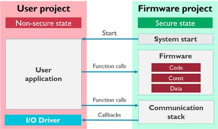
TrustZone projects achieve isolation through a hardware mechanism that breaks the embedded software into a user project (non-secure) and a firmware project (secure) .
A microcontroller that enables TrustZone will boot into the secure state and start the system before jumping into the non-secure state to execute the user application.
Summary
TrustZone就是將一個物理處理器分為兩個邏輯處理器,一半是Rich Execution Environment 另一半是Trusted Execution Environment。其作用可相當於在一個虛擬化的環境中: 一個虛擬機器執行Rich System,另外一個虛擬機器執行Trust System。
由於其硬體隔離的特性,從Rich Execution Environment很難直接操作Trust那邊的程式碼和資源,所以能夠極大的提高各種基於ARM的應用環境的安全性。
實際上, 一個ARMv8的處理器上可以執行兩個獨立的作業系統: 一個是執行在Rich Execution Environment上的Linux,另外一個就是執行在Trusted Execution Environment之上的小系統.
TrustZone只是一個硬體隔離技術,如果願意, 完全可以在Trusted Execution Environment上面再跑一個Linux,但是系統越小,越緊湊,目的越單純越安全。
Modern software expects to be split into different modules, each with a different level of access to system and processor resources.
Armv8-A and Armv9-A enables this split by implementing different levels of privilege.
These privilege levels are referred to as Exception levels in the Arm architecture because the current level of privilege can only change when the processor takes or returns from an exception.
The Exception levels are referred to as EL<x>, with x as a number between 0 and 3.

- application code running at EL0
- an operating system running at EL1
- EL2 is used by a hypervisor
- EL3 being reserved by low-level firmware and security code
- 在Rich側,有EL0/EL1/EL2三個執行級別分別對應一個作業系統的使用者態,核心態,虛擬化態。
- 在Trusted側,只有EL0/EL1兩個執行級別,對應的作業系統的使用者態和核心態,所以在ARM處理器的Trust側並不支援硬體虛擬化。
所以要使用一個完整的帶TrustZone支援的Linux,你需要
- 在Linux側有驅動程式發出SMC指令從而切換到Trust側的OS
- 在Trust側的OS處理完成之後同樣需要通過SMC(驅動或者系統呼叫)指令切換回Rich側的Linux。
Memory Layout
Normal Boot
+--------------+----------------+
|BLD           |    2.5 MB      |
+--------------+----------------+
|Linux         | Total - 2.5 MB |
+--------------+----------------+
Secure Boot without Arm Trustzone
+--------------+----------------+
|ATF(BL2)      |    512 KB      |
+--------------+----------------+
|ATF(BL31)     |    512 KB      |
+--------------+----------------+
|BLD(BL33)     |    3.5 MB      |
+--------------+----------------+
|Linux         | Total - 4.5 MB |
+--------------+----------------+
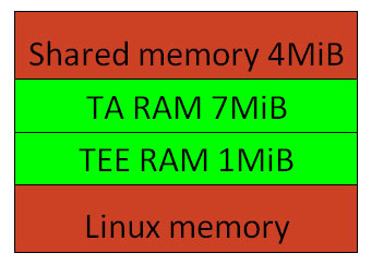
Secure Boot with Arm Trustzone
+-----------------+--------------+----+-------+
| Secure World    |ATF(BL2)      |    |512 KB |
| Memory          +--------------+    +-------+
|                 |ATF(BL31)     |    |512 KB |
|                 +--------------+----+-------+
|                 |OPTEE(BL32)   |TEE |1 MB   |
|                 |              +----+-------+
|                 |              | TA |10 MB  |
+-----------------+--------------+----+-------+
|Normal World     | EL2 RSVD     |    4 MB    |
|memory           +--------------+------------+
|                 |Shared memory |    4 MB    |
|                 +--------------+------------+
|                 |BLD(BL33)     |    2.5 MB  |
|                 +--------------+------------+
|                 |Linux         |Total-22.5MB|
+-----------------+--------------+------------+
Introduction to Trusted Execution Environment and ARM's TrustZone
A Trusted Execution Environment (TEE) is an environment where the code executed and the data accessed is isolated and protected :- confidentiality no one have access to the data
- integrity no one can change the code and its behavior
This is what we call a Trusted Execution Environment or TEE.
TEE usages
TEE would be a good solution to storage and manage the device encryption keys that could be used to verify the integrity of the operating system.TEE is well-suited for isolating resources within a device to store the biometric algorithm, user credentials and associated data.
TEE terminology and operation
In a system with a TEE, we have- untrusted applications running on a Rich Execution Environment (REE)
- trusted applications (TAs) running on a Trusted Execution Environment (TEE)

Bare metal is a computer system without a base operating system (OS). Applications for the bare metal systems are BIOS or boot loader.
In TEE, we need a secure boot feature to check the integrity and authenticity of all operating system components (bootloaders, kernel, filesystems, trusted applications, etc).
We need the hardware support to partition and isolate the hardware (busses, peripherals, memory regions, interrupts, etc) so that the running code does not have access to protected resources.
How ARM’s TrustZone works?
Usually, an ARM Cortex-A processor has 3 execution modes:- user mode
- kernel mode
- hypervisor mode
When operating in this the secure monitor mode, the CPU is in the Secure World and can access all of the device’s peripherals and memory.
The transition from the Secure World to the Non-Secure World is via a dedicated instruction called Secure Monitor Call (SMC).
When this instruction is executed, the CPU will enter in monitor mode. At this moment, we can run the TEE firmware/operating system.

- the untrusted application will use an API to send the request to the Linux kernel
- the TrustZone drivers will send the request to the TEE OS via SMC instruction
- the TEE OS will pass along the request to the trusted application
We can leverage existing implementations such as OP-TEE (Open Portable Trusted Execution Environment).
Trusted Execution Environment (TEE) Overview
TEE provides an isolated environment to ensure code/data integrity and confidentiality.TEE adds an additional layer of security where code/data running on the TEE can not be accessed/tampered from the normal Linux.
The trusted applications are meant to handle confidential information and provide services to the normal world Linux to make use of the confidential information.
How is TEE implemented?
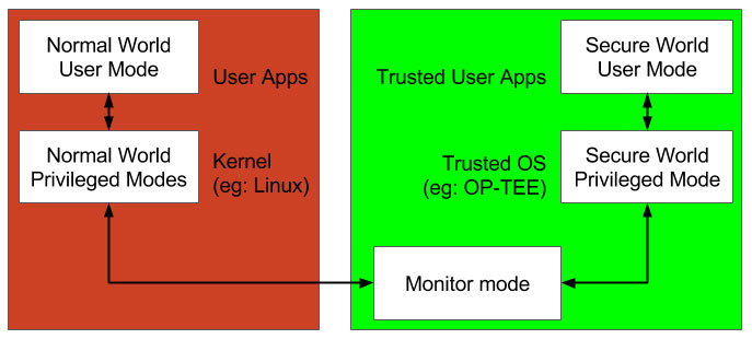
TEE requires both software and hardware (built into the processor) support.- On the hardware side ARM based processors achieve TEE using TrustZone technology. TrustZone enables a single physical processor core to execute code safely and efficiently from both the normal world (Linux/Android) and the secure world (Security OS like OP-TEE).
- On the software side There is a normal world OS (eg: Linux) and a secure world OS (eg: OP-TEE). Both OSs are running in the priviledge mode.
TrustZone implements a ‘state’ based memory and IO protection. i.e. when the processor is running in the secure state/context (secure world), it has a different view of the system and has access to memory/peripherals that normally can not be accessed from a non-secure state/context (normal world).
Simplified hardware view of ARM TrustZone security:
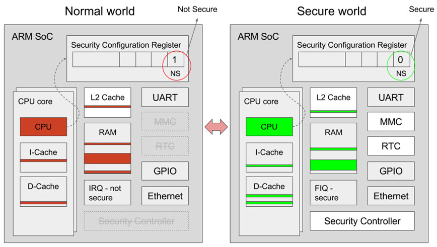
Similarly, there are user applications in normal world and trusted user applications in secure world both running in user mode.
The secure world OS
Global Platform, a nonprofit organization, has developed TEE API and Framework specifications to standardize TEE .There are various specifications available for TEE Client, Core, etc.
That sepecifications specify interactions between:
- a Trusted Application and Secure World OS
- a Trusted Application with another Trusted Application
- a Client Application with a Trusted Application
- ...
Open-source Portable TEE (OP-TEE)
OPTEE is a open source implementation of TEE.OP-TEE comprises of :
- secure world OS (optee_os)
- normal world client (optee_client)
- test suite (optee_test/xtest)
- Linux driver

- The CA uses the TEE client API to talk to the TA and requests secure services from it.
- The CA and TA used shared memory to pass data between each other.
Getting started with OP-TEE
There are options to build the OP-TEE software:- Minimal OP-TEE build system To help jump start running OP-TEE, some board maintainers (eg: Raspberry Pi 3 and TI AM43xx/AM57xx) provide a minimal build system that generates all the required images (bootloaders, OP-TEE OS, Linux kernel, OP-TEE client and a minimal RFS).
- Yocto Project build system Include the meta-optee layer in your build and add the relevant packages to local.conf.
- Manual Cross-compile and build the various parts Refer to CI scripts. An example for i.MX6/7 platform can be found here.
Refer to build and manifest projects
For a custom board with a different memory size, you might need to adjust the platform configuration file:
- the secure memory location (CFG_TEE_RAM_START, CFG_TA_RAM_START)
- the shared memory location(CFG_SHMEM_START)
- Some platforms also allow the code to run from internal SRAM (CFG_WITH_PAGER).
Bootloader support and boot flow
Using OMAP platform as an example to explain th eboot process:- the first program being run after power-on is ROM code (which is similar to BIOS on PC).
- ROM code looks for bootloader The bootloader must be a file named "MLO" and located on active first partition of MMC, which must be formatted as FAT12/16/32, -- but that's details)
- ROM code copies content of that "MLO" file to static RAM (because regular RAM is not initialized yet). The SRAM memory layout for OMAP4460,
- initialize regular RAM and copy regular bootloader from MMC to RAM
- jump to execute that regular bootloader
- ROM code is the first thing that loads (and executes) other program
- SPL is the second thing that loads (and executes) other program.
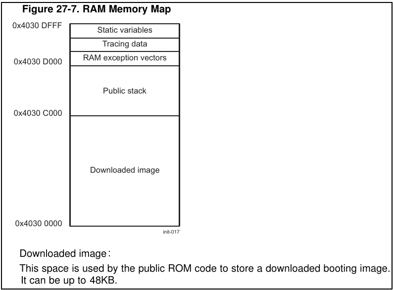
SRAM memory is limited (due to physical reasons), so we only have 48 KiB for bootloader.
Usually regular bootloader (e.g. U-Boot) binary is bigger than that.
So we need to create some additional bootloader, which will:
This first-stage bootloader is U-Boot SPL(Secondary Program Loader.); and second-stage bootloader is regular U-Boot (or U-Boot proper).
This naming is due to the facts:
+----------------+----------------+----------------+----------+
| Boot           | Terminology #1 | Terminology #2 | Actual   |
| stage          |                |                | program  |
| number         |                |                | name     |
+----------------+----------------+----------------+----------+
| 1              |  Primary       |  -             | ROM code |
|                |  Program       |                |          |
|                |  Loader        |                |          |
|                |                |                |          |
| 2              |  Secondary     |   1st stage    | u-boot   |
|                |  Program       |  bootloader    | SPL      |
|                |  Loader (SPL)  |                |          |
|                |                |                |          |
| 3              |  -             |  2nd stage     | u-boot   |
|                |                |  bootloader    |          |
|                |                |                |          |
| 4              |  -             |  -             | kernel   |
|                |                |                |          |
+----------------+----------------+----------------+----------+
Ideally, the OP-TEE binary must be loaded as early as possible in the boot process.

- the ROM bootloader loads/executes a 1st stage bootloader (eg: SPL, MLO, SBL1, FSBL)
- the 1st stage bootloader executes a 2nd stage bootloader (eg: U-Boot, LittleKernel)
- the 2nd stage bootloader executes the Linux kernel, all from a secure world context
On an ARMv7 based processor, the typical boot flow with TEE is:
- SPL loads OP-TEE and U-Boot SPL jumps to OP-TEE and once OP-TEE is done with initialization, it switches to non-secure context and jumps to U-Boot.
- The OP-TEE code will continue to reside in memory to provide secure services to the Linux kernel.
On an ARMv8 based processor, the TEE boot flow involves an additional step
- SPL loading ARM Trusted firmware, along with OP-TEE and U-Boot. SPL jumps to arm trusted firmware which later hands control to OP-TEE which in-turn jumps to U-Boot in non-secure context.
On an ARMv8 platform, ARM Trusted firmware provides the monitor code to manage the switch between secure and non-secure world, whereas it is built-in to OP-TEE for ARMv7 platforms.
Linux support
A Linux kernel driver for OP-TEE is available in kernel 4.12 or higher.Enable the driver with following below steps:
- Set CONFIG_OPTEE=y in your kernel config
- Add device tree nodes for OP-TEE as shown here
- Alternatively compiling OP-TEE OS with CFG_DT=y can modify the dtb at runtime to add the required nodes
Troubleshooting OP-TEE issues
Once you have bootloader, Linux and OP-TEE OS running, you may potentially run into issues on your custom board.
- Imprecise aborts These are typically seen when a secure peripheral and/or memory is being accessed by the normal world OS.
- Memory map conflicts The load address and runtime address of OP-TEE OS and kernel/dtb/ramfs need to be reviewed carefully, otherwise it could lead to issues like the kernel trying to relocate itself to the OP-TEE runtime region, etc.
- Clock setup Linux kernel disables clocks to any unused peripherals but the peripheral might be used by the secure world OS which Linux is not aware of.
- Resource conflict If a peripheral is being accessed by both normal and secure world code, there is no locking mechanism which could lead to conflicts.
It is recommended to review the permissions of peripheral/memory regions.
One way to work around this is to include “clk_ignore_unused” as part of Linux kernel bootargs.
In the absence of a locking mechanism, it is recommended that only one of the world owns access to the resource and that it provide services to the other world to interact with the resource.
Trusted Applications (TA)

- include/
/* This UUID is generated with uuidgen
   the ITU-T UUID generator at http://www.itu.int/ITU-T/asn1/uuid.html */
#define TA_HELLO_WORLD_UUID { 0x8aaaf200, 0x2450, 0x11e4, \
		{ 0xab, 0xe2, 0x00, 0x02, 0xa5, 0xd5, 0xc5, 0x1b} }

/* The Trusted Application Function ID(s) implemented in this TA */
#define TA_HELLO_WORLD_CMD_INC_VALUE	0
/* OP-TEE TEE client API (built by optee_client) */
#include <tee_client_api.h>

/* To the the UUID (found the the TA's h-file(s)) */
#include <hello_world_ta.h>

int main(int argc, char *argv[])
{
	TEEC_Result res;
	TEEC_Context ctx;
	TEEC_Session sess;
	TEEC_Operation op;
	TEEC_UUID uuid = TA_HELLO_WORLD_UUID;
	...
	/* Initialize a context connecting us to the TEE */
	res = TEEC_InitializeContext(NULL, &ctx);
	...
	/*
	 * Open a session to the "hello world" TA, the TA will print "hello
	 * world!" in the log when the session is created.
	 */
	res = TEEC_OpenSession(&ctx, &sess, &uuid,
			       TEEC_LOGIN_PUBLIC, NULL, NULL, &err_origin);
	...
    /*
	 * Prepare the argument. Pass a value in the first parameter,
	 * the remaining three parameters are unused.
	 */
	op.paramTypes = TEEC_PARAM_TYPES(TEEC_VALUE_INOUT, TEEC_NONE,
					 TEEC_NONE, TEEC_NONE);
	op.params[0].value.a = 42;

    /*
	 * TA_HELLO_WORLD_CMD_INC_VALUE is the actual function (ID) in the TA to be
	 * called.
	 */
	printf("Invoking TA to increment %d\n", op.params[0].value.a);
	res = TEEC_InvokeCommand(&sess, TA_HELLO_WORLD_CMD_INC_VALUE, &op,
				 &err_origin);
	TEEC_CloseSession(&sess);

	TEEC_FinalizeContext(&ctx);

	return 0;
}
Basic data structure:
TEEC_Result res;
TEEC_Context ctx;  // Represents a connection between a client application and a TEE.
typedef struct {// Implementation defined
    int fd;
    bool reg_mem;
} TEEC Context;

TEEC_Session sess; // Represents a connection between a client application and a trusted application.
typedef struct { // Implementation defined
    TEEC Context *ctx;
    uint32 t session_id;
} TEEC Session;

TEEC_Operation op; // Holds information and memory references.
TEEC_UUID uuid;    // UUID values are used to identify Trusted Applications.
Basic functions:
TEEC_InitializeContext(&ctx) /* Initialize a context */
TEEC_OpenSession(&ctx, &sess, &uuid) /* Open a session */
TEEC_InvokeCommand(&sess, cmd, &op, & err_origin)
TEEC_CloseSession(&sess); /* Close the session*/
TEEC_FinalizeContext(&ctx); /* Destory the context*/
...
# The UUID for the Trusted Application
BINARY=8aaaf200-2450-11e4-abe2-0002a5d5c51b

-include $(TA_DEV_KIT_DIR)/mk/ta_dev_kit.mk
...
#include <hello_world_ta.h> /* To get the TA_HELLO_WORLD_UUID define */

#define TA_UUID TA_HELLO_WORLD_UUID

#define TA_FLAGS                    (TA_FLAG_MULTI_SESSION | TA_FLAG_EXEC_DDR)
#define TA_STACK_SIZE               (2 * 1024)
#define TA_DATA_SIZE                (32 * 1024)

#define TA_CURRENT_TA_EXT_PROPERTIES \
    { "gp.ta.description", USER_TA_PROP_TYPE_STRING, \
        "Hello World TA" }, \
    { "gp.ta.version", USER_TA_PROP_TYPE_U32, &(const uint32_t){ 0x0010 } }
#define STR_TRACE_USER_TA "HELLO_WORLD"
#include <tee_internal_api.h>
#include <tee_internal_api_extensions.h>
#include "hello_world_ta.h"
/*
* Called when the instance of the TA is created. This is the first call in
* the TA.
*/
TEE_Result TA_CreateEntryPoint(void)
{
DMSG("has been called");
return TEE_SUCCESS;
}
/*
* Called when the instance of the TA is destroyed if the TA has not
* crashed or panicked. This is the last call in the TA.
*/
void TA_DestroyEntryPoint(void)
{
DMSG("has been called");
}
/*
* Called when a new session is opened to the TA. *sess_ctx can be updated
* with a value to be able to identify this session in subsequent calls to the
* TA. In this function you will normally do the global initialization for the
* TA.
*/
TEE_Result TA_OpenSessionEntryPoint(uint32_t param_types,
TEE_Param __maybe_unused params[4],
void __maybe_unused **sess_ctx)
{
uint32_t exp_param_types = TEE_PARAM_TYPES(TEE_PARAM_TYPE_NONE,
TEE_PARAM_TYPE_NONE,
TEE_PARAM_TYPE_NONE,
TEE_PARAM_TYPE_NONE);
if (param_types != exp_param_types)
return TEE_ERROR_BAD_PARAMETERS;
/* Unused parameters */
(void)¶ms;
(void)&sess_ctx;
/*
* The DMSG() macro is non-standard, TEE Internal API doesn't
* specify any means to logging from a TA.
*/
DMSG("Hello World!\n");
/* If return value != TEE_SUCCESS the session will not be created. */
return TEE_SUCCESS;
}
/*
* Called when a session is closed, sess_ctx hold the value that was
* assigned by TA_OpenSessionEntryPoint().
*/
void TA_CloseSessionEntryPoint(void __maybe_unused *sess_ctx)
{
(void)&sess_ctx; /* Unused parameter */
DMSG("Goodbye!\n");
}
static TEE_Result inc_value(uint32_t param_types,
TEE_Param params[4])
{
uint32_t exp_param_types = TEE_PARAM_TYPES(TEE_PARAM_TYPE_VALUE_INOUT,
TEE_PARAM_TYPE_NONE,
TEE_PARAM_TYPE_NONE,
TEE_PARAM_TYPE_NONE);
DMSG("has been called");
if (param_types != exp_param_types)
return TEE_ERROR_BAD_PARAMETERS;
DMSG("Got value: %u from NW", params[0].value.a);
params[0].value.a++;
DMSG("Increase value to: %u", params[0].value.a);
return TEE_SUCCESS;
}
/*
* Called when a TA is invoked. sess_ctx hold that value that was
* assigned by TA_OpenSessionEntryPoint(). The rest of the paramters
* comes from normal world.
*/
TEE_Result TA_InvokeCommandEntryPoint(void __maybe_unused *sess_ctx,
uint32_t cmd_id,
uint32_t param_types, TEE_Param params[4])
{
(void)&sess_ctx; /* Unused parameter */
switch (cmd_id) {
case TA_HELLO_WORLD_CMD_INC_VALUE:
return inc_value(param_types, params);
#if 0
case TA_HELLO_WORLD_CMD_XXX:
return ...
break;
case TA_HELLO_WORLD_CMD_YYY:
return ...
break;
case TA_HELLO_WORLD_CMD_ZZZ:
return ...
break;
...
#endif
default:
return TEE_ERROR_BAD_PARAMETERS;
}
}
Basic data structure:
/*
 * The macro TEE_PARAM_TYPES can be used to construct a value that you can
 * compare against an incoming paramTypes to check the type of all the
 * parameters in one comparison, like in the following example:
 * if (paramTypes != TEE_PARAM_TYPES(TEE_PARAM_TYPE_MEMREF_INPUT,
 *                                  TEE_PARAM_TYPE_MEMREF_OUPUT,
 *                                  TEE_PARAM_TYPE_NONE, TEE_PARAM_TYPE_NONE)) {
 *      return TEE_ERROR_BAD_PARAMETERS;
 *  }
 */
#define TEE_PARAM_TYPES(t0,t1,t2,t3) \
   ((t0) | ((t1) << 4) | ((t2) << 8) | ((t3) << 12))

/*
 * This union describes one parameter passed by the Trusted Core Framework
 * to the entry points TA_OpenSessionEntryPoint or
 * TA_InvokeCommandEntryPoint or by the TA to the functions
 * TEE_OpenTASession or TEE_InvokeTACommand.
 *
 * Which of the field value or memref to select is determined by the
 * parameter type specified in the argument paramTypes passed to the entry
 * point.
*/
typedef union {
	struct {
		void *buffer;
		uint32_t size;
	} memref;
	struct {
		uint32_t a;
		uint32_t b;
	} value;
} TEE_Param;
There are 2 types of trusted apps:
- Dynamic Dynamic Apps reside in the normal world file system (RFS) and gets loaded into the secure world user space at runtime when a Linux client application wants to use it.
- Pseudo/Static Psuedo/Static Apps are typically built as part of the OP-TEE kernel and run in kernel mode.
The TAs are signed and OP_TEE OS verifies the signature before executing.
These apps mostly deal with providing services that involve controlling hardware which is difficult to implement in Dynamic App that runs in user space.
The data is stored either on the Linux filesystem (/data/tee) in encrypted/authenticated (AES-GCM) manner or on an eMMC RPMB partition.
Real world example
TEE can be used to play a dedicated security chip role (key storage or crypto authentication) with a software solution:
- Develop a TEE client app as part of OpenSSL engine to interface with the TA
- The Trusted Application needs to implement handlers for key management and crypto operations. OP-TEE OS includes libtomcrypt which provides various symmetric/asymmetric/elliptic curve cryptography functions.

ARM Trusted Firmware分析——启动、PSCI、OP-TEE接口

1. 冷啟動(Cold boot)流程及階段劃分
- BL1 - AP Trusted ROM,一般为 BootRom。
- BL2 - Trusted Boot Firmware,一般为 Trusted Bootloader。
- BL31 - EL3 Runtime Firmware,一般为SML,管理SMC执行处理和中断,运行在secure monitor中。
- BL32 - Secure-EL1 Payload,一般为 TEE OS Image。
- BL33 - Non-Trusted Firmware,一般为uboot、linux kernel。

BL1
BL1位於ROM中,在EL3下從reset vector處開始運行。BL1做的工作主要有:
- 決定啟動路徑:冷啟動還是熱啟動。
- 架構初始化:異常向量、CPU復位處理函數配置、控制寄存器設置(SCRLR_EL3/SCR_EL3/CPTR_EL3/DAIF)
- 平台初始化:使能Trusted Watchdog、初始化控制台、配置硬件一致性互聯、配置MMU、初始化相關存儲設備。
- 固件更新處理
- BL2鏡像加載和執行:
- BL1輸出“Booting Trusted Firmware"。
- BL1加載BL2到SRAM;如果SRAM不夠或者BL2鏡像錯誤,輸出“Failed to load BL2 firmware.”。
- BL1切換到Secure EL1並將執行權交給BL2.
BL2
BL2位於SRAM中,運行在Secure EL1主要工作有:- 架構初始化:EL1/EL0使能浮點單元和ASMID。
- 平台初始化:控制台初始化、相關存儲設備初始化、MMU、相關設備安全配置、
- SCP_BL2:系統控制核鏡像加載,單獨核處理系統功耗、時鐘、復位等控制。
- 加載BL31 image(ATF):BL2將控制權交給BL1;BL1關閉MMU並關cache;BL1將控制權交給BL31。
- 加載BL32 image(TOS):BL32運行在安全世界,BL2依賴BL31將控制權交給BL32。 SPSR通過Secure-EL1 Payload Dispatcher進行初始化。
- 加載BL33 images:BL2依賴BL31將控制權交給BL33。
BL31
BL31位於SRAM中,EL3模式。除了做架構初始化和平台初始化外,還做瞭如下工作:- PSCI服務初始化,後續提供CPU功耗管理操作。
- BL32鏡像運行初始化,處於Secure EL1模式。
- 初始化非安全EL2或EL1,跳轉到BL33執行。
- 負責安全非安全世界切換。
- 進行安全服務請求的分發。
4. BL31(EL3 Firmware)
Refer to 《SMC CALLING CONVENTION System Software on ARM® Platforms》
Secure Monitor Call is an ARM assembler instruction that causes an exception that is taken synchronously into EL3.
The SMC instruction is used to generate a synchronous exception that is handled by Secure Monitor code running in EL3.
The arguments are passed in registers and then used to select which Secure function to execute.
These calls may then be passed on to a Trusted OS in S-EL1.
Secure Key Services in OP-TEE
Secure Services can be provided by- Hardware Security Module (HSM)
- Secure Elements as Smartcard, SIM cards.
- Trusted Platform Modules (TPM devices)
- Trusted Execution Environment (TEE)
- Key materials and cryptographic operations are very hard to tamper with.
- Client can import, generate, derive keys and cipher, sign, authenticate data.
- Secure keys have usage constraints.
- Use of secure keys may require user authentication.

- Secure Storage relates functions
- TEE_CreatePersistentObject()
- TEE_OpenPersistentObject()
- TEE_CloseAndDeletePersistentObject1()
- TEE_ReadObjectData()
- TEE_WriteObjectData()
- TEE_TruncateObjectData()
- TEE_SeekObjectData()
- Cryptographic operations functions
- TEE_DigestInit/Update/DoFinal()
- TEE_CipherInit/Update/DoFinal()
- TEE_MACInit/Update/ComputeFinal/CompareFinal()
- TEE_DeriveKey()
- TEE_AEInit/AEUpdateAAD/AEUpdateAAD/AEEncryptFinal/AEDecryptFinal()
- TEE_AsymmetricEncrypt/Decrypt/SignDigest/VerifyDigest()
- TEE_GenerateKey()

OP-TEE: Architecture
Core
Interrupt handling
This section describes how optee_os handles switches of world execution context based on SMC exceptions and interrupt notifications.This section lists all the cases where OP-TEE OS is involved in world context switches:
- When the normal world invokes the secure world, the normal world executes a SMC exceptions. The SMC exception is always trapped by the Monitor.
- When a secure interrupt is signaled by the Arm GIC(Generic Interrupt Controller), it shall reach the OP-TEE OS interrupt exception vector.
- If the secure world is executing, OP-TEE OS will handle interrupt straight from its exception vector.
- If the normal world is executing when the secure interrupt raises, the Monitor vector must handle the exception and invoke OP-TEE OS to serve the interrupt.
- When a non-secure interrupt is signaled by the Arm GIC, it shall reach the normal world interrupt exception vector.
- If the normal world is executing, it will handle straight the exception from its exception vector.
- If the secure world is executing when the non-secure interrupt raises, OP-TEE OS will temporarily return back to normal world via the Monitor to let normal world serve the interrupt.
If the related service targets the trusted OS, the Monitor will switch to OP-TEE OS world execution.
When the secure world completes the request, OP-TEE OS executes a SMC that is caught by the Monitor which switches back to the normal world.
Secure Storage
Background
Secure Storage in OP-TEE is implemented according to what has been defined in GlobalPlatform’s TEE Internal Core API (here called Trusted Storage).This specification mandates that it should be possible to store general-purpose data and key material that guarantees confidentiality and integrity of the data stored.
There are currently two secure storage implementations in OP-TEE:
- REE FS Secure Storage It is enabled at compile time by CFG_REE_FS=y.
- RPMB Secure Storage. It is enabled by setting CFG_RPMB_FS=y. I

REE FS Secure Storage
Basic File Operation Flow
When a TA is calling the write function provided by GP Trusted Storage API to write data to a persistent object, a corresponding syscall implemented in TEE Trusted Storage Service will be called, which in turn will invoke a series of TEE file operations to store the data.TEE file system will then encrypt the data and send REE file operation commands with the encrypted data to TEE supplicant by a series of RPC messages.
TEE supplicant will receive the messages and store the encrypted data accordingly to the Linux file system.
GlobalPlatform Trusted Storage Requirement
- The Trusted Storage may be backed by non-secure resources as long as suitable cryptographic protection is applied
- The Trusted Storage MUST be accessible or modifiable only by authorized TAs running in the same TEE and on the same device as when the data was created.
- Ability to hide sensitive key material from the TA itself.
- Each TA has access to its own storage space
TEE File Structure in Linux File System
OP-TEE by default uses /data/tee/ as the secure storage space in the Linux file system.Key Manager
Key manager is a component in TEE file system, and is responsible for handling- data encryption and decryption
- management of the sensitive key materials
- the Secure Storage Key (SSK)
- the TA Storage Key (TSK)
- the File Encryption Key (FEK)
Secure Storage Key (SSK)
SSK(Secure Storage Key) is a per-device key and is generated and stored in secure memory when OP-TEE is booting.SSK is derived from
(HUK, Chip ID || “static string”)Currently, in OP-TEE OS, we only have a per-device key, SSK.
SSK is used to derive the TA Storage Key (TSK).
The TSK is a per-TA key, which is generated from the SSK and the TA’s identifier (UUID).
TSK is derived by:
TSK = HMACSHA256 (SSK, TA_UUID)
TSK is used to protect the FEK(File Encryption Key), in other words, to encrypt/decrypt the FEK.
When a new TEE file is created, key manager will generate a new FEK for the TEE file and store the encrypted FEK in meta file.
FEK is used for encrypting/decrypting the TEE file information stored in meta file or the data stored in block file.
Hash Tree
Build and run
How to build OP-TEE as a whole developer setup or as individual components and how to run OP-TEE on various devices.
Prerequisites
To be able to build and run OP-TEE there are a few packages that needs to be available.- enable installation of i386 architecture packages and update the package managers database.
$ sudo dpkg --add-architecture i386
$ sudo apt-get update
$ mkdir -p ~/bin
$ curl https://storage.googleapis.com/git-repo-downloads/repo > ~/bin/repo
$ chmod a+x ~/bin/repo
$ sudo apt-get install android-tools-adb android-tools-fastboot autoconf \
        automake bc bison build-essential ccache codespell cpio \
        cscope curl device-tree-compiler expect flex ftp-upload gdisk acpica-tools \
        libattr1-dev libcap-dev libcap-ng-dev \
        libfdt-dev libftdi-dev libglib2.0-dev libgmp-dev libhidapi-dev \
        libmpc-dev libncurses5-dev libpixman-1-dev libssl-dev libtool make \
        mtools netcat ninja-build python-crypto python3-crypto python-pyelftools \
        python3-pycryptodome python3-pyelftools python3-serial \
        rsync unzip uuid-dev xdg-utils xterm xz-utils zlib1g-dev
Device specific information
QEMU v7
To fetch, build and run OP-TEE using QEMU for Armv7-A$ repo init -u https://github.com/OP-TEE/manifest.git $ repo sync $ cd build $ make toolchains # Note that if you wish to debug optee-os or a TA, you should disable ASLR # with flag "CFG_CORE_ASLR=n" $ make run CFG_CORE_ASLR=n ... * QEMU is now waiting to start the execution * Start execution with either a 'c' followed by <enter> in the QEMU console or * attach a debugger and continue from there. * * To run OP-TEE tests, use the xtest command in the 'Normal World' terminal * Enter 'xtest -h' for help. # Option “-x” is deprecated and might be removed in a later version of gnome-terminal. # Option “-x” is deprecated and might be removed in a later version of gnome-terminal. # Use “-- ” to terminate the options and put the command line to execute after it. # Use “-- ” to terminate the options and put the command line to execute after it. cd /home/work/optee/build/../out/bin && /home/work/optee/build/../qemu/build/arm-softmmu/qemu-system-arm \ -nographic \ -serial tcp:localhost:54320 -serial tcp:localhost:54321 \ -smp 2 \ -s -S -machine virt,secure=on -cpu cortex-a15 \ -d unimp -semihosting-config enable=on,target=native \ -m 1057 \ -bios bl1.bin \ -object rng-random,filename=/dev/urandom,id=rng0 -device virtio-rng-pci,rng=rng0,max-bytes=1024,period=1000 -netdev user,id=vmnic -device virtio-net-device,netdev=vmnic QEMU 6.0.0 monitor - type 'help' for more information (qemu)
QEMU v8
To fetch, build and run OP-TEE using QEMU for Armv8-A :$ repo init -u https://github.com/OP-TEE/manifest.git -m qemu_v8.xml $ repo sync $ cd build $ make toolchains # Note that if you wish to debug optee-os or a TA, you should disable ASLR # with flag "CFG_CORE_ASLR=n" $ make runAfter running make run you will end up in the QEMU console and it will also spawn two UART consoles.
One console containing the UART for secure world and one console containing the UART for normal world:
listening on port 54320
soc_term: accepted fd 4
soc_term: read fd EOF
soc_term: accepted fd 4
listening on port 54321
soc_term: accepted fd 4
soc_term: read fd EOF
soc_term: accepted fd 4
You can launch another console for GDB:
$ cd <qemu-v7-project>/toolchains/aarch32/bin
$ ./arm-linux-gnueabihf-gdb -q
in the GDB console, load the symbols for TEE core:
(gdb) symbol-file <qemu-v7-project>/optee_os/out/arm/core/tee.elf
Reading symbols from <qemu-v7-project>/optee_os/out/arm/core/tee.elf...done.
Linux kernel TEE framework
OP-TEE gits
Trusted Software Development Using OP-TEE
About OP-TEE(Open Portable Trusted Execution Environment)
OP-TEE is a Trusted Execution Environment (TEE) designed as companion to a non-secure Linux kernel running on Arm.OP-TEE implements :
- the TEE Internal Core API v1.1.x the API exposed to Trusted Applications.
- the TEE Client API v1.0 the API describing how to communicate with a TEE.
OP-TEE is designed primarily to rely on the Arm TrustZone technology as the underlying hardware isolation mechanism.
TEE Internal Core API Specification
2 Overview of the TEE Internal Core API Specification
2.1 Trusted Applications
A Trusted Application (TA) is a program that runs in a Trusted Execution Environment (TEE) and exposes security services to its Clients.Clients access a Trusted Application by opening a session with the Trusted Application and invoking commands within the session.
When a Trusted Application receives a command, it parses the messages associated with the command, performs any required processing, and then sends a response back to the client.
- A Client typically runs in the Rich Execution Environment and communicates with a Trusted Application using the TEE Client API [Client API]. It is then called a “Client Application”.
- It is also possible for a Trusted Application to act as a client of another Trusted Application
2.1.1 TA Interface
Each Trusted Application exposes an interface (the TA interface) composed of a set of entry point functions that the Trusted Core Framework implementation calls to inform the TA about life cycle changes and to relay communication between Clients and the TA.

Each Trusted Application is identified by a Universally Unique Identifier (UUID) and comes with a set of Trusted Application Configuration Properties.
4.3 TA Interface
Each Trusted Application SHALL provide the Implementation with a number of functions, collectively called the “TA interface”.These functions are the entry points called by the Trusted Core Framework to create the instance, notify the instance that a new client is connecting, notify the instance when the client invokes a command, etc.
TA Interface Functions:
- TA_CreateEntryPoint This is the Trusted Application constructor. It is called once and only once in the lifetime of the Trusted Application instance. If this function fails, the instance is not created.
- TA_DestroyEntryPoint This is the Trusted Application destructor. The Trusted Core Framework calls this function just before the Trusted Application instance is terminated. The Framework SHALL guarantee that no sessions are open when this function is called. When TA_DestroyEntryPoint returns, the Framework SHALL collect all resources claimed by the Trusted Application instance.
- TA_OpenSessionEntryPoint This function is called whenever a client attempts to connect to the Trusted Application instance to open a new session.
- TA_CloseSessionEntryPoint This function is called when the client closes a session and disconnects from the Trusted Application instance.
- TA_InvokeCommandEntryPoint This function is called whenever a client invokes a Trusted Application command.
In this function, the Trusted Application can attach an opaque void* context to the session. This context is recalled in all subsequent TA calls within the session.
- TEEC_OpenSession or TEE_OpenTASession TA_CreateEntryPoint is called, then, TA_OpenSessionEntryPoint is called.
- TEEC_InvokeCommand or TEE_InvokeTACommand TA_InvokeCommandEntryPoint is called.
- TEEC_CloseSession or TEE_CloseTASession TA_CloseSessionEntryPoint is called.
- TEEC_RequestCancellation or The function TEE_OpenTASession or TEE_InvokeTACommand is cancelled.

4.3.1 TA_CreateEntryPoint
4.9 Internal Client API
This API allows a Trusted Application to act as a client to another Trusted Application.4.9.1 TEE_OpenTASession
The function TEE_OpenTASession opens a new session with a Trusted Application.
TEE_Result TEE_OpenTASession(
        [in] TEE_UUID* destination,
        uint32_t cancellationRequestTimeout,
        uint32_t paramTypes,
        [inout] TEE_Param params[4],
        [out] TEE_TASessionHandle* session,
        [out] uint32_t* returnOrigin);
The destination Trusted Application is identified by its UUID passed in destination.4.9.2 TEE_CloseTASession
The function TEE_CloseTASession closes a client session.void TEE_CloseTASession(TEE_TASessionHandle session);
4.9.3 TEE_InvokeTACommand
The function TEE_InvokeTACommand invokes a command within a session opened between the client 1619 Trusted Application instance and a destination Trusted Application instance.
        TEE_Result TEE_InvokeTACommand(
        TEE_TASessionHandle session,
        uint32_t cancellationRequestTimeout,
        uint32_t commandID,
        uint32_t paramTypes,
        [inout] TEE_Param params[4],
        [out] uint32_t* returnOrigin);
- commandID The identifier of the Command to invoke.
The meaning of each Command Identifier SHALL be defined in the protocol exposed by the target Trusted Application.
References
1. https://blog.csdn.net/Neutionwei/article/details/114915307
2. https://blog.csdn.net/chenying126/article/details/78638944
3. https://www.timesys.com/security/trusted-software-development-op-tee/
4. OPTEE https://www.slideshare.net/linaroorg/tee-kernel-support-is-now-upstream-what-this-means-for-open-source-security-76943254?next_slideshow=1
5. ARMV8-M中的TrustZone如何保护代码的安全?

留言