BIOS
需要了解的SMBIOS知識
SMBios (System Management BIOS) 與 DMI (desktop management Interface) 一個叫Distributed Management Task Force 組織定義了一些data structure,規定BIOS裡面必須提供一些資料,像是CPU, 主機板廠商型號等等資料。資料結構對外的interface為DMI ,他規定了這些資料要放在哪些特定的記憶體位址讓大家讀取而不是雜亂的亂放。
說穿了就是一堆資訊分門別類而已.
Both SMBIOS and DMI standards are tightly related and developed by the DMTF (Desktop Management Task Force).
什麼是SMBIOS
SMBIOS (System Management BIOS) 是一個標準 由 DMTF所開發,這個標準的目的是允許作業系統去獲取電腦的資訊。在設定SMBIOS方面,我們會在Memory的某個地方建立一個Table. 經由解析這個Table,它是可以存取電腦資訊和電腦屬性。
每個主機板廠商或者OEM廠商所生產的電腦,在出廠的時候都會按照SMBIOS標準把資訊寫入到BIOS中。主要就是包含可電腦各個模組資訊。
廠商將這些資訊寫好存入到BIOS晶片中,這部分資訊是屬於BIOS的一部分。在UEFI中屬於專門的一個驅動模組
SMBIOS, which was actually called DMIBIOS in its first revisions.
什麼是DMI
DMI exposes system data (including the System Management BIOS (SMBIOS) data) to management software, but the two specifications function independently.DMI(Desktop Management Interface)包含有關於系統硬體的配置資訊,DMI通常将資訊存储在BIOS中一个4KB大小的DMI database中,MIFD(Management Information Format Database)。
DMI就是在嚴格遵照SMBIOS規範的前提下進行收集電腦系統信息的管理系統。
通過DMI,OS可以獲取序列號,電腦廠商,串列埠資訊以及其他系統配件資訊。
DMI充當了管理工具和系統層之間接口的角色。
DMI被設計為一個能夠在任何平台和操作系統下實現的接口規範,它允許人員在該database中手工添加一些BIOS無法檢測到的用戶信息姓名、銷售和計算機編號等額外的控制 ,因此我們也可以不用對 BIOS 進行操作的情況下使用 DMI 對 MIFD 中的系統配置情況進行修改以適應不同環境下的系統要求。
dmidecode - DMI table decoder
dmidecode is a tool for dumping a computer's DMI (some say SMBIOS) table contents in a human-readable format.Thanks to this table, you can retrieve this information without having to probe for the actual hardware.
dmidecode will try to locate the DMI table. It will first try to read the DMI table from sysfs, and next try reading directly from memory if sysfs access failed.
If dmidecode succeeds in locating a valid DMI table, it will then parse this table and display a list of records.
Each record has:
- A handle This is a unique identifier, which allows records to reference each other. For example, processor records usually reference cache memory records using their handles.
- A type The SMBIOS specification defines different types of elements a computer can be made of.
       Type   Information
       --------------------------------------------
          0   BIOS
          1   System
          2   Baseboard
          3   Chassis
          4   Processor
          5   Memory Controller
          6   Memory Module
          7   Cache
          8   Port Connector
          9   System Slots
         10   On Board Devices
         11   OEM Strings
         12   System Configuration Options
         13   BIOS Language
         14   Group Associations
         15   System Event Log
         16   Physical Memory Array
         17   Memory Device
         18   32-bit Memory Error
         19   Memory Array Mapped Address
         20   Memory Device Mapped Address
         21   Built-in Pointing Device
         22   Portable Battery
         23   System Reset
         24   Hardware Security
         25   System Power Controls
         26   Voltage Probe
         27   Cooling Device
         28   Temperature Probe
         29   Electrical Current Probe
         30   Out-of-band Remote Access
         31   Boot Integrity Services
         32   System Boot
         33   64-bit Memory Error
         34   Management Device
         35   Management Device Component
         36   Management Device Threshold Data
         37   Memory Channel
         38   IPMI Device
         39   Power Supply
         40   Additional Information
         41   Onboard Devices Extended Information
         42   Management Controller Host Interface
Keywords can be used instead of type numbers with --type. Each keyword is equivalent to a list of type numbers:
       Keyword     Types
       ------------------------------
       bios        0, 13
       system      1, 12, 15, 23, 32
       baseboard   2, 10, 41
       chassis     3
       processor   4
       memory      5, 6, 16, 17
       cache       7
       connector   8
       slot        9
Keywords are matched case-insensitively. The following command lines are equivalent:
dmidecode --type 0 --type 13
dmidecode --type 0,13
dmidecode --type bios
dmidecode --type BIOS
ACPI (Advanced Configuration and Power Interface)
古老的 APM 與 PnP BIOS , 系統會針對有些 Event做動作,像 fan 不會轉,laptop 的蓋子蓋下後,進入省電模式等等。ACPI規格的立義就是要讓作業系統來做這些統一的控制Operating System-directed configuration and Power Management (OSPM)。
ACPI 跟 SMBIOS DMI 的差別還有 ACPI 不光是有靜態資料結構的定義,他還有控制的程式介面定義。
如果支援 ACPI ,就等於在 kernel space 時,把控制權交給外來的 byte code 處理,OS 本身不處理硬體控制,而這些外來 byte code 如果不是 open source 的,安全與可靠性都相當令人擔憂,所以 open source 對這些寫爛 code 的公司相當反感。
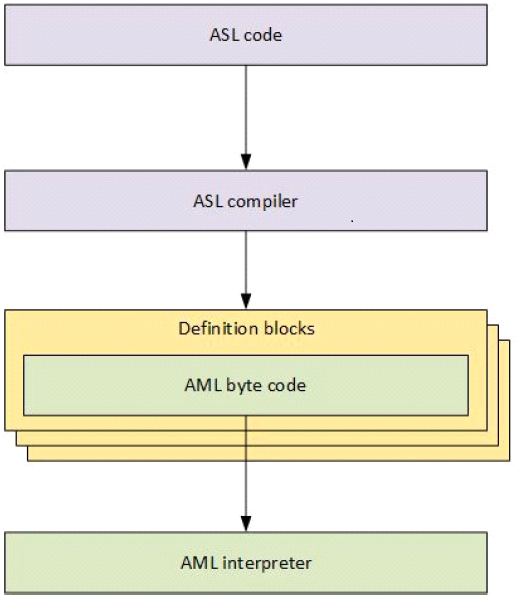
ACPICA 組織提供了一些工具,來編譯 ASL 成 hex 與 aml 檔。也能反組 AML 成 ASL 檔案。
$ sudo cat /sys/firmware/acpi/tables/DSDT > dsdt.dat
$ iasl -d dsdt.dat # disassemble to dsdt.dsl
Before the development of ACPI, operating systems (OS) primarily used BIOS (Basic Input/Output System) interfaces for power management and device discovery and configuration.
This required developers to learn how to configure power management for each individual system.
ACPI can first be understood as an architecture-independent power management and configuration framework that forms a subsystem within the host OS.
This framework establishes a hardware register set to define power states (sleep, hibernate, wake, etc).
The primary intention of the standard ACPI framework and the hardware register set is to enable power management and system configuration without directly calling firmware natively from the OS.
ACPI serves as an interface layer between the operating system and system firmware(BIOS), as shown in the following figure.
ACPI defines two types of data structures that are shared between system firmware and the OS via the ACPI subsystem:
- data tables Data tables store raw data and are consumed by device drivers.
- definition blocks Definition blocks consist of byte code that is executable by an interpreter.
The definition block byte code is compiled from the ACPI Source Language (ASL) code.
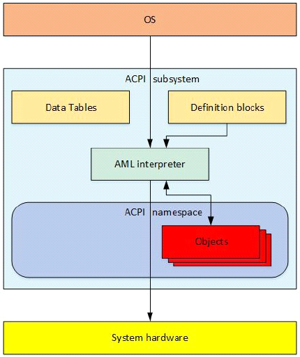
This collection of enumerable objects forms an OS construct called the ACPI namespace.
The AML interpreter has read/write access to defined address spaces, including system memory, I/O, PCI configuration, and more.
The AML interpreter, directed by the OS, evaluates objects and then interfaces with system hardware to perform necessary operations.
The namespace is a hierarchical representation of the ACPI devices on a system.
The system bus is the root of enumeration for these ACPI devices.
Devices that are enumerable on other buses, like PCI or USB devices, are usually not enumerated in the namespace.
ACPI Initialization
The system firmware(BIOS) then uses information obtained during firmware initialization to update the ACPI tables as necessary with various platform configurations and power interface data, before passing control to the bootstrap loader.The extended root system description table (XSDT) is the first table used by the ACPI subsystem and contains the addresses of most of the other ACPI tables on the system.
The XSDT points to the fixed ACPI description table (FADT) as well as other major tables that the OS processes during initialization.
After the OS initializes, the FADT directs the ACPI subsystem to the differentiated system description table (DSDT), which is the beginning of the namespace because it is the first table that contains a definition block.
The ACPI subsystem then processes the DSDT and begins building the namespace from the ACPI definition blocks.
After the OS has built the namespace from the ACPI tables, it begins traversing the namespace and loading device drivers for all the _HID devices it encounters in the namespace.
After the system is up and running, ACPI works with the OS to handle any ACPI events that occur via an interrupt.
How to create a bootable USB media to access the default EFI shell
- Format a USB device in FAT32.
- Create a directory on the USB device:
- Copy the file shell.efi to the directory created above.
- Rename the file shell.efi to BOOTX64.efi
- Restart the system and enter the UEFI menu.
- Select the option to Boot from USB.
/efi/boot/
Some of the most common EFI Shell commands.
- clear the outputs of the screen
Shell> cls
Shell> echo "Hello World"
Shell> alias
Shell> help m*
Shell> set
Shell> set file boot.img
By default, the EFI Shell environment variables you create will survive system reboots. You can create volatile EFI Shell environment variables using the set command’s -v option.
To remove the EFI Shell environment variable
Shell> set -d file
Shell> map
UEFI Shell Scripting Tutorial
UEFI (Unified EFI – Extensible Firmware Interface) is a software specification used to interface between the operating system and the firmware of your computer’s hardware.
You can use it to run EFI Shell commands and run your own EFI scripts.
UEFI Shell Script Extension
The UEFI or EFI Shell script files have the extension nsh.So, the UEFI or EFI Shell scripts you create should end with .nsh.
Writing Your First UEFI/EFI Shell Script
In this example, all the scripts are in the FS0 storage device.You can use a USB thumb drive or any other storage device. It must be FAT-32 or FAT-16 formatted for this to work.
You can navigate to the FS0 storage device with the following EFI Shell command:
Shell> FS0:You should have only an EFI directory on your FS0 storage device.
FS0:\> ls

留言