Raspberry Pi : Equipment
| Part | Function | Implemented Device | GPIO (BRCM) |
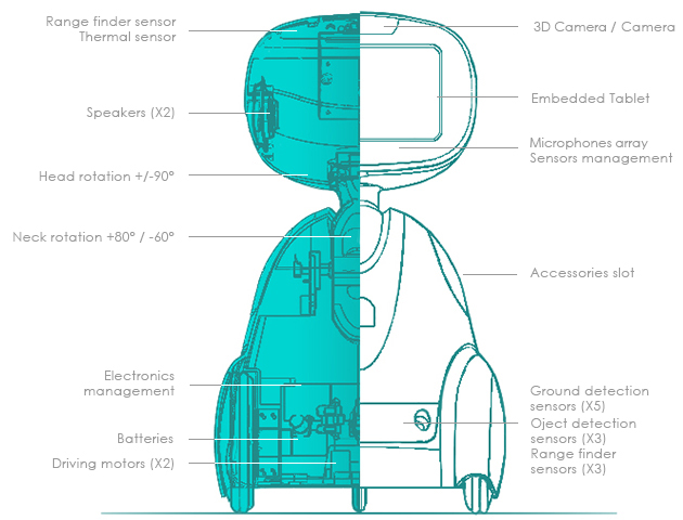
| Head | Position Indicator | Red LED | |
| Motion Detection | Pi Camera | 15-pin MIPI Camera Serial Interface (CSI-2) | |
| Distance Detection | Ultrasound Sensor | TRIGER_OUT=5 ECHO_IN=6 | |
| Human Detection | PIR | IN=24 | |
| Ear | Microphone | USB | |
| Mouth | Speaker | 3.5mm jack | |
| Neck | Head Rotation | Stepper Motor | IN1=17 IN2=27 IN3=22 IN4=23 |
| Body | Heart | Raspberry Pi | GPIO x 26 |
| Messages | LCD display | ||
| Batery | USB Battery | ||
| Front Obstacle Detection | IR TxRx | IN=25 | |
| Wall Detection | IR TxRx | ||
| Legs | 4WD + 2 DC motors |


Equipment
Raspberry PI Model B+ 512MB
The Raspberry Pi Model B+ incorporates a number of enhancements and new features. Improved power consumption, increased connectivity and greater IO are among the improvements to this powerful, small and lightweight ARM based computer.規格與 Model B 相同,不同處如下:
* 5V 電源供應增加了一個 2A 的保險絲,因此新版可熱插拔 USB。
* 新的 USB/Ethernet 控制晶片。
* 4 個 USB 埠(原為 2 個埠)。。
* 40 個 GPIO 腳位(原為 26 個腳位)。
* Composite (NTSC/PAL) 視訊輸出和 3.5mm 耳機插孔整合在一起。
* 使用 microSD 卡做為儲存設備(原為 SD 卡)。
* 電路板邊緣做導角設計。
* 將多個接頭移到同一側
Specifications
- Chip Broadcom BCM2835 SoC
- Core architecture ARM11
- CPU 700 MHz Low Power ARM1176JZFS Applications Processor
- GPU Dual Core VideoCore IV® Multimedia Co-Processor Provides Open GL ES 2.0, hardware-accelerated OpenVG, and 1080p30 H.264 high-profile decode Capable of 1Gpixel/s, 1.5Gtexel/s or 24GFLOPs with texture filtering and DMA infrastructure
- Memory 512MB SDRAM
- Operating System Boots from Micro SD card, running a version of the Linux operating system
- Dimensions 85 x 56 x 17mm
- Power Micro USB socket 5V, 2A
Connectors
- Ethernet 10/100 BaseT Ethernet socket
- Video Output HDMI (rev 1.3 & 1.4) Composite RCA (PAL and NTSC)
- Audio Output 3.5mm jack, HDMI
- USB 4 x USB 2.0 Connector
- GPIO Connector 40-pin 2.54 mm (100 mil) expansion header: 2x20 strip Of the 40 pins, 26 are GPIO pins and the others are power(+3.3 V, +5 V) or ground pins (plus two ID EEPROM pins which you should not play with unless you know your stuff!)
- Camera Connector 15-pin MIPI Camera Serial Interface (CSI-2)
- JTAG Not populated
- Display Connector Display Serial Interface (DSI) 15 way flat flex cable connector with two data lanes and a clock lane
- Memory Card Slot SDIO

3w大功率樹莓派夜視攝像頭專用紅外補光燈
- 3W / 3.3V = 0.9 A
- The Pi itself wants about 800mA@5V
Featues
--3W high-power 850 infrared LED ,Voltage Range: 3.3-5V --Onboard photoresistor, the ambient light detector --Onboard adjustable resistor, for controlling the ambient light threshold of toggling the infrared LED --Allows adding night vision function to RPi Camera (E) or RPi Camera (F)How to Use
1.Connect the Infrared LED Board to the camera PCB by screws 2. The screw holes are used for both attachment and power supply 3. Adjust the adjustable resistor to set a proper ambient light threshold, which toggles the infrared LED automatically 4. When ambient light is lower than threshold value, the infrared LED is on, vice versaNote
Limited by the Raspberry Pi power supply, the 3W high-power infrared LED might cause the Pi to increase heating, heat sinks are suggested. Ideal imaging distance is within 3m. When the distance goes up to 6m, the night vision camera can just capture blurry outlines.l
TECPEL泰菱電子直購網 》 UNI-T 優利德 UT 136A 3 3/4 電錶+自動量程 三用電表: $630.
Infra-red LED
An Infra-red light-emitting diode (LED) is an LED which emits light in the infra-red spectrum providing night vision to an infra-red camera. Female-to-Female Jumper Cable: Jumper cables are used to connect electronic components to each other and to the Raspberry Pi's GPIO pins. 220R Resistorresistor = (supply voltage - LED voltage) / LED current in Amps
So for 3.3V supply and 2.0V LED at 5mA (for a fairly dim LED, but won't break GPIO): (3.3 - 2.0) / 0.005 = 260 Ohms. Closest resistor is 270 Ohm
BH1750FVI I2C Digital Light Intensity Sensor
Sensor that can pick up insect activity
I had some time tonight so I bead boarded a simple circuit using an LED, a phototransistor,and an OP Amp. I hooked an oscilloscope up to the output of the Op Amp so I could monitor any signal that might be generated. I put a dark cover over the phototransistor with a darkened f-stop in front of it to give it tunnel vision. Opposite it on the circuit board I had a yellow LED also inside a cover with its output shining directly at the f-stop in front of the photo transistor. I used a piece of thread as the simulation of one of your insects. The thread was 0.26 mm wide. When I put the thread quickly through the space between the LED and the phototransistor it triggered the oscilloscope and recorded the signal.
Here is a picture of the circuit I used and the piece of string.

Here are pictures of the bread board and sensor setup. If you click on the pictures they will get bigger.


The last picture is a bitmap of what the oscilloscope saw when the thread was dragged past the gap between the LED and the Phototransistor. While this may or may not be the way you want to go it at least shows you a proof of concept.
- an ISL28218 Op Amp
- a regular LED housed in a black rubber tube
- a TEPT5600 photo transistor also housed in a black rubber tube
How to Use LEDs to Detect Light
LEDs have a much smaller light-sensitive surface than most silicon photodiodes, so they’re more likely to require amplification. Inexpensive operational amplifiers are ideal. Figure D shows a simple circuit I often use to convert the photocurrent from an LED into a proportional voltage. The Linear Technology LT1006 single-supply op-amp (IC1) provides a voltage output that’s almost perfectly linear with respect to the intensity of the incoming light. The gain or amplification equals the resistance of the feedback resistor (R1). Thus, when R1 is 1,000,000 ohms, the gain of the circuit is 1,000,000. Capacitor C1 prevents oscillation.
Why Use LEDs As Sensors?
Silicon photodiodes are widely available and inexpensive. So why use LEDs as light sensors?LEDs detect a narrow band of wavelengths, which is why I call them spectrally selective photodiodes. A silicon photodiode has a very broad spectral response, about 400nm (violet) to 1,000nm (invisible near-IR), and requires an expensive filter for detecting a specific wavelength.
The sensitivity of most LEDs is very stable over time. So are silicon photodiodes — but filters have limited life.
LEDs can both emit and detect light. This means an optical data link can be established with only a single LED at each end, since separate transmitting and receiving LEDs aren’t needed.
LEDs are even more inexpensive and widely available than photodiodes.
Drawbacks of LEDs As Light Sensors
No sensor is perfect.LEDs are not as sensitive to light as most silicon photodiodes.
LEDs are sensitive to temperature. This can pose a problem for outdoor sensors. One solution is to mount a temperature sensor close to the LED so a correction signal can be applied in real time or when the data are processed.
Some LEDs I’ve tested do gradually lose their sensitivity.
LEDs Detect Specific Colors of Light
The typical human eye responds to light with wavelengths from around 400nm (violet) to about 700nm (red). LEDs detect a much narrower band of light, having a peak sensitivity at a wavelength slightly shorter than the peak wavelength they emit. For example, an LED with a peak emission in the red at 660nm responds best to orange light at 610nm.The spectral width of light emitted by typical blue, green, and red LEDs ranges from about 10nm—25nm. Near-IR LEDs have a spectral width of 100nm or more. The sensitivity of most LEDs I’ve tested provides ample overlap to detect light from an identical LED.
Blue and most green LEDs are made from gallium nitride (GaN). The brightest red LEDs are made from aluminum gallium arsenide (AlGaAs). The LEDs used in near-infrared remote controllers are also AlGaAs devices; their peak emission is about 880nm and peak detection around 820nm.
Older remote controllers used gallium arsenide compensated with silicon (GaAs:Si). These LEDs emit at about 940nm, which makes them ideal for detecting water vapor, but they’ve become very difficult to find.
In my experience, the sensitivity of red “super-bright” and AlGaAs LEDs and similar near-IR LEDS is very stable over many years of use. Green LEDS made from gallium phosphide (GaP) are also very stable. However, a blue LED made from GaN has declined in sensitivity more than any LED I have used.
NOTE:
This does not apply to white LEDs, which are blue-emitting LEDs coated with a phosphor that glows yellow and red when stimulated by blue from the LED. The merging of the blue, yellow, and red provides white light. While a white LED can detect blue light, a blue LED is a much better choice.
Basic LED Sensor Circuits
You can substitute an LED for a standard silicon photodiode in most circuits. Just be sure to observe polarity. Also, remember that the LED isn’t as sensitive as most standard photodiodes and will respond to a much narrower band of light wavelengths.
For best results, use LEDs encapsulated in clear epoxy and try a few experiments first. These will help you understand how the detection angle of an LED used as a sensor matches its emission angle when used as a light source:
Use standard couplers to attach LEDs to plastic optical fiber, or attach them directly using this method (Figure B): Flatten the top of the LED with a file, clamp it securely, and carefully bore a small hole just above the light-emitting chip. Insert the fiber and cement it in place.
Connect the leads of a clear encapsulated red or near-IR LED to a multimeter set to indicate current. Point the LED toward the sun or a bright incandescent light, and the meter will indicate a current (Figure C).
Use one LED to power a second LED. Connect the anode and cathode leads of 2 clear encapsulated super-bright red LEDs. When one LED is illuminated with a bright flashlight, the second LED will glow. Heat-shrink tubing is placed over the glowing LED to block light from the flashlight. You can see this working in the photo at the top of the article.

LEDs have a much smaller light-sensitive surface than most silicon photodiodes, so they’re more likely to require amplification. Inexpensive operational amplifiers are ideal. Figure D shows a simple circuit I often use to convert the photocurrent from an LED into a proportional voltage. The Linear Technology LT1006 single-supply op-amp (IC1) provides a voltage output that’s almost perfectly linear with respect to the intensity of the incoming light. The gain or amplification equals the resistance of the feedback resistor (R1). Thus, when R1 is 1,000,000 ohms, the gain of the circuit is 1,000,000. Capacitor C1 prevents oscillation.
Many other op-amps can be substituted for the LT1006, but most of them require a dual-polarity power supply. If you use one of these, connect pin 4 directly to the negative supply. Connect pin 3 and the cathode of the LED to ground (the junction between the minus side F of the positive supply and the positive side of w the minus supply).
Parts and Equipment
編號
| ||||||||||||||||||||||||||||||||||||||||||||||||||||||||||||||||||||||||||||||||||||||||||||||||||||||||||||||||||
| 商品 | 單價 | 數量 | 總價 | ||||||||||||||||
|---|---|---|---|---|---|---|---|---|---|---|---|---|---|---|---|---|---|---|---|
|
|
|
|
| |||||||||||||||
|
|
|
|
| |||||||||||||||
|
|
|
|
| |||||||||||||||
|
|
|
|
| |||||||||||||||
|
|
|
|
| |||||||||||||||
| ( DC 3 - 5.5V ) 低功耗、超音波感測模組升級版 (HC-SR04+) | 單件60元 適用合併運費規則 | 125元 | 1 | 125 元 | ||
| {3V3} 整合型{4/8BIT,IIC,4SPI}1602英文字型藍底白字LCD螢幕(附排針)-適用於樹莓派,微控制器 | 單件60元 適用合併運費規則 | 240元 | 1 | 240 元 | ||
| 5.0V 迷你降壓模組 - AMS1117 | 單件60元 適用合併運費規則 | 38元 | 1 | 38 元 | ||
| 3.3V 迷你降壓模組 - AMS1117 | 單件60元 適用合併運費規則 | 38元 | 1 | 38 元 | ||
| L298N 馬達驅動板( 2 直流 / 1 步進) (可用於樹莓派, Arduino, 單晶片, 8051, AVR) | 單件60元 適用合併運費規則 | 150元 | 1 | 150 元 | ||
GY-521 6軸 模組 三軸加速度 三軸陀螺儀 MPU 6050 6DOF GY 521
Arduino 紅外線發射傳感器產品編號: 2430000006975
NT$ 45.
S 連接GPIO,VCC 接+5V,GND 接 GND
●小功率正向電流:20mA
●小功率正向電壓:1.1~1.5V
●中功率正向電流:50~100mA
●中功率正向電壓:1.4~1.65V
●大功率正向電流:200~350mA
●大功率正向電壓:1.5~1.9V
●尺寸:35x15.5x6mm
Arduino 紅外線接收傳感器產品編號: 2430000006852
NT$ 45.
●S 連接GPIO,VCC 接+5V,GND 接 GND
●
●接收角度:90°
●工作電壓:2.7~5.5V
●頻率:37.9KHZ
●接收距離:18M
●採用內、外雙遮罩封裝結構,抗光、電磁干擾能力強,內置紅外線專用IC,能在500LUX光線強度下正常工作
●尺寸:23.5x15.4x12.5mm
Arduino 紅外線避障傳感器產品型號: IR-08H 產品編號: 2430000007842
NT$ 100.
●工作電壓:DC3.3V~5V
●工作電流:≥20mA
●工作溫度:-10℃~+50℃
●檢測距離:2~40cm
●輸出信號:TTL電平(有障礙物低電平,無障礙物高電平)
●調節方式:多圈電阻式調節
●有效角度:35°
●尺寸:48x17.3x11.5mm
紅外避障傳感器是專為輪式機器人設計的一款距離可調式避障傳感器。此傳感器對環境光線適應能力強、精度高,其具有一對紅外線發射與接收管,發射管發射出一定頻率的紅外線,當檢測方向遇到障礙物(反射面)時,紅外線反射回來被接收管接收,此時指示燈亮起,經過電路處理後,信號輸出接口輸出數字信號,可通過電位器旋鈕調節檢測距離。由於工作電壓範圍寬泛,在電源電壓波動比較大的情況下仍能穩定工作,適合多種單片機、Arduino控制器、BS2控制器使用,安裝到機器人上即可感測周圍環境的變化。


At the heart of the sensor is an NE555 chip configured to generate a 38kHz square wave. (The IR-08H uses an SN74LS00.)
The 38kHz signal is used to illuminate an Infra Red (IR) LED.
Light reflected from the LED is detected by a Vishay HS0038B IR receiver module (see data sheet).

The receiver module incorporates an external, optical, 950nm IR filter and an internal, electronic, 38kHz band-pass filter that make the module receptive only to IR light pulsing at that frequency.
One of the potentiometers on the board (R6) is used to fine tune the signal to exactly 38kHz.
The other (R5) adjusts the duty cycle of the signal, which controls the brightness of the IR LED.
Both adjustments together effect the sensitivity or range of the device. Proper adjustment of R6 requires an oscilloscope or a frequency counter. Otherwise it can be left centered or as it came from the manufacturer.
The receiver module also includes an AGC (Automatic Gain Control) that will suppress a continuous signal of any frequency, including 38kHz (see excerpt from data sheet, below). Therefore, it is absolutley necessary to use the 'EN' or 'Enable' pin for proper operation of the device. If the Enable function is used correctly, the device will achieve its maximum sensitivity.
On most versions of this device, the Infra Red (IR) LED is already covered with a small piece of black shrink tubing; but I find that additional optical shielding is required. A small cardboard tube commonly used as packing material will work satisfactorily, as will a variety of other materials.
When the GREEN JUMPER is installed on the board (see picture), the IR LED will flicker continuously at 38kHz. If the Enable (EN) function will not be used, the jumper must be installed . When the jumper is removed, pin 4 of the 555 timer is held LOW (RESET) by R3, a 22K pull-down resistor. Then, if a HIGH condition is applied to the EN pin, the reset condition will be relieved and the 555 timer will begin to oscillate. The Enable function cannot be used if the GREEN JUMPER is in place. You must remove the jumper on the board in order to use the EN (Enable) pin.
Working voltage: 3.3V to 5V DC
Working current: ≥ 20mA
Operating temperature: -10°C  to +50°C
Detection distance: 2 to 40cm
IO Interface: 4-pin (EN / +V / S / GND)
Output signal: TTL level
LOW level if obstacle detected
HIGH if no obstacle detected
Adjustment: two single-turn variable resistors
Effective angle: ±35°
Size: 28mm × 23mm
Weight: 9g

Sample C++ code to strobe the IR LED with a 600µs pulse and test for a return:

digitalWrite( enablePin, HIGH);     // Enable the internal 38kHz signal.
microDelay( 210);                   // Wait 210µs (8 pulses of 38kHz).
if( digitalRead( outputPin))        // If detector Output is HIGH,
{
    objectDetect = false;           // then no object was detected;
}
else                                // but if the Output is LOW,
{
    microDelay( 395);               // wait for another 15 pulses.
    if( digitalRead( outputPin))    // If the Output is now HIGH,
    {                               // then first Read was noise
        objectDetect = false;       // and no object was detected;
    }
    else                            // but if the Output is still LOW,
    {
        objectDetect = true;        // then an object was truly detected.
    }
}
digitalWrite( enablePin, LOW);      // Disable the internal 38kHz signal.

1.感應到物體輸出0,未感應到時輸出1,可直接與3V和5V單片机IO口相連。
2.感應距離2到30厘米,距離遠,抗干擾能力好。(注意:紅外傳感器不是檢測所有的物體都能得到一樣的距離的,不同顏色的物體對光線的反射率不同,物體的顏色越深越接近黑色檢測的距離就越短,本傳感器2到30厘米是對著白色的墻測量出來的)
3.速度快,適合智能小車避障、黑白線循跡、防跌落,產品計數器,流水線切割,液位檢測等。
4.用此傳感器制作的黑白線尋跡小車無需在白紙黑線上跑,可在水泥地,黃泥地等復雜的環境黑線巡跡。只要黑線周邊的顏色比黑色略淺即可,消除了傳統的走法,令環境布置更加簡單。
5.本傳感器3至6V供電,范圍超寬,適合3V和5V的單片机系統。
6.帶使能端,EN端等于“1”時傳感器不工作,等于“0”時工作。傳感器上跳帽插上后EN端長期接地(EN長期為“0”)。要使用EN端時請把跳帽拿掉。
7.頻率調節電位器用來調節紅外發射管的載波頻率,因為一體化接收頭要在特定的38KHZ載波頻率的時候才是最靈敏的。將502電阻順時針調到盡(也就是將發射管的亮度調到最大),然后對准白色的墻調103電阻,一直調到感應距離是最遠為止,這樣傳感器就工作在最佳狀態了
Arduino 觸摸開關模組產品編號: 2430000010118
此模組是一個基於觸摸檢測IC(TTP223B)的電容式點動型觸摸開關模組。常態下,模組輸出低電平,模式為低功耗模式;當用手指觸摸相應位置時,模組會輸出高電平,模式切換為快速模式;當持續12秒沒有觸摸時,模式又切換為低功耗模式。可以將模組安裝在非金屬材料如塑膠、玻璃的表面,另外將薄薄的紙片(非金屬)覆蓋在模組的表面,只要觸摸的位置正確,即可做成隱藏在牆壁、桌面等地方的按鍵。該模組可以讓你免除常規按壓型按鍵的煩惱。
NT$ 45.
●控制介面:GND為地,VCC為電源,SIG為數位信號輸出腳
●電壓:2.0-5.5V
●輸出引腳灌電流:8mA
●輸出引腳拉電流:-4mA
●回應時間(低功耗模式):220mS
●回應時間(快速模式):60mS
●尺寸:24X24X7.2mm
●重量:2g
DC5V 小步進馬達產品型號: 28BYJ-48-5V 產品編號: 2090000001242
NT$ 70.
步進電必須加驅動才可以運轉,驅動信號必須為脈衝信號,沒有脈衝的時候,步進馬達靜止,如果加入適當的脈衝信號,就會按照一定的角度(簡稱為步角)轉動。
轉動特定速度和脈衝基礎頻率成正比。
步進馬達具有瞬間啟動和快速停止的優越特性。
改變脈衝的順序,可以方便改變轉動的方向。
目前打印機,繪圖儀,機器人等設備都以步進馬達為動力的核心。

●額定電壓:5(V)
●額定電流:0.005-5(A)
●步進角度:5.625 x 1/64
●减速比:1/64
●直徑:28mm
●外形尺寸:24*19(mm)
| 編號 | 商品 | 單價 | 數量 | 總價 | |||||||||||||||
|---|---|---|---|---|---|---|---|---|---|---|---|---|---|---|---|---|---|---|---|
|
|
|
|
| |||||||||||||||
|
|
|
|
| |||||||||||||||
|
|
|
|
| |||||||||||||||
Arduino PIR 人體檢測電子積木模組 人體熱釋電感測模組 傳感器
編號: CSH0008
人體熱釋電傳感器用於檢測運動的人或者動物身上發出的紅外線,本產品採用專用紅外檢測頭,靈敏度高、體積小、穩定可靠,開關電平量輸出,使用方便,板載指示燈,方便監測檢測結果,100°散射角,檢測範圍大,適用於人體運動檢測、運動報警器等等。
產品規格:
尺寸:30*21*12mm
固定孔:3mm
孔距:15mm
輸入電壓:5V
輸出:數字電平3V高電平(LED亮) 0V低電平
輸出電流:1ma
輸出延時:3秒左右
感應角度:100°
感應距離:6m左右
接口:Arduino 3P接口SVG
平台:Arduino、單片機

留言