SNR, RSSI, EIRP and Free Space Path Loss
What is a logarithm? A brief introduction.
First let's look at exponents. If we write 102 or 103 , we mean
- 102 = 10*10 = 100 and 103 = 10*10*10 = 1000.
- 101 = 10.
- 10-n = 1/10n
- (102)3 = (100)3 = 100*100*100 = 1,000,000 = 106.
- (10n)m = 10nm.
- 10log a = a.
- 3.16232 = (10log 3.1623)2 = 10 = 101.
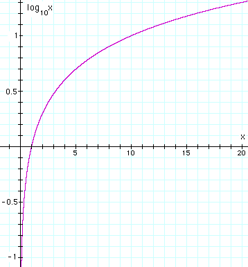
A few other important examples are worth noting. 100 would have the property that, no matter how many times you multiplied it by itself, it would never get as large as 10. Further, no matter how many times you divided it into 1, you would never get as small as 1/10. Using our (10n)m = 10nm rule, you will see that 100 = 1 satisfies this, so the log of one is zero. The log of 2 is used often in acoustics, and it is 0.3010 (see graph at right).
Hence, a factor of 2 in power corresponds to 3.01 dB, which we should normally write as 3 dB.
dB: What is a decibel?

Definition and examples
The decibel ( dB) is used to measure sound level, but it is also widely used in electronics, signals and communication. The dB is a logarithmic way of describing a ratio. The ratio may be power, sound pressure, voltage or intensity or several other things. Later on we relate dB to the phon and the sone (related to loudness). But first, to get a taste for logarithmic expressions, let's look at some numbers. (For instance, suppose we have two loudspeakers, the first playing a sound with power P1, and another playing a louder version of the same sound with power P2, but everything else (how far away, frequency) kept the same.
10 log (P2/P1) dB where the log is to base 10.
If the second produces twice as much power than the first, the difference in dB is
10 log (P2/P1) = 10 log 2 = 3 dB.
as is shown on the graph, which plots 10 log (P2/P1) against P2/P1. To continue the example, if the second had 10 times the power of the first, the difference in dB would be
10 log (P2/P1) = 10 log 10 = 10 dB.
If the second had a million times the power of the first, the difference in dB would be
10 log (P2/P1) = 10 log 1,000,000 = 60 dB.
This example shows one feature of decibel scales that is useful in discussing sound: they can describe very big ratios using numbers of modest size. But note that the decibel describes a ratio: so far we have not said what power either of the speakers radiates, only the ratio of powers. (Note also the factor 10 in the definition, which puts the 'deci' in decibel).
https://supportforums.cisco.com/document/49506/snr-rssi-eirp-and-free-space-path-loss
Introduction
SNR, RSSI, EIRP and Free Space Path Loss
Signal to Noise Ratio
The power level of the RF signal relative to the power level of the noise floor is known as the Signal-to-Noise ratio or SNR. It is the ratio of signal power to the noise power corrupting the signal.
In simple words, SNR (Signal-to-Noise Ratio) is a ratio based value that evaluates your signal based on the noise being seen. SNR is measured as a positive value between 0dB and 120dB and the closer the value is to 120dB, the better.
Let's look at the components of the SNR and then understand how SNR is determined. SNR is comprised of 2 values.
- a) Signal
- b) Noise
RSSI (Received Signal Strength Indicator) is a more common name for the Signal value. It is the strength that one device is hearing another device. This value is measured in decibels from 0 (zero) to -120 (minus 120). The closer this value to 0 (zero), stronger the signal.
Typically voice networks require a -65dBm or better signal level while a data network needs -80dBm or better. Normal range in a network would be -45dBm to -87dBm depending on power levels and design. The Signal is also affected by the APs transmit power & antenna as well as the client's antenna.
Noise is any signal that interferes with your signal. Noise can be due to other wireless devices such as cordless phones, microwave devices etc. This value is measured in decibels from 0 (zero) to -120 (minus 120). Noise level is the amount of interference in your wireless signal, so lower is better. Looking at this value, if the value is closer to -120 (minus 120) it is better because that means there is little to no interference. Typical environments range between -90dBm and -98dBm.
To calculate the SNR value, we add the Signal Value to the Noise Value and it generates (or should) a positive number that is expressed in decibels (db). For example, lets say your Signal value is -55dBm and your Noise value is -95dBm.
-55dBm + -95dBm = 40db this means you have an SNR of 40, the general rule of thumb is that any SNR above 20 is good.
Other important terminologies that we need to understand is the EIRP and Free Space Path Loss.
EIRP (Effective Isotropic Radiated Power)
EIRP (Effective Isotropic Radiated Power) is the actual amount of signal leaving the antenna and is a value measured in db and is based on 3 values:
a) Transmit Power (dBm)
b) Cable Loss (dB)
c) Antenna Gain (dBi)
a) Transmit Power (dBm)
b) Cable Loss (dB)
c) Antenna Gain (dBi)
The dB measures the power of a signal as a function of its ratio to another standardized value. The abbreviation dB is often combined with other abbreviations in order to represent the values that are compared. Here are two examples:
dBm—The dB value is compared to 1 mW.
dBw—The dB value is compared to 1 W.
You can calculate the power in dBs from this formula:
Power (in dB) = 10 * log10 (Signal/Reference)
This list defines the terms in the formula:
This list defines the terms in the formula:
log10 is logarithm base 10.
Signal is the power of the signal (for example, 50 mW).
Reference is the reference power (for example, 1 mW).
How to find EIRP
To determine EIRP follow this equation:
For example we have a Cisco 1242AG access points running at full power with a 6dBi antenna on the 802.11a radio and a 2.5dBi antenna on the 802.11bg radio.
802.11a EIRP = 17dBm (40mw) - 0dB + 6dBi = 23dBm = 200mw of actual output power
802.11bg EIRP = 20dBm (100mw) - 0dB + 2.5dBi = 22.5dBm = 150mw (approx) of actual output power
Based on the example above, in theory, if you were to measure it right at the antenna you could get an RSSI of -23dBm or -22.5dBm respectively.
Free Space Path Loss
Free space path loss is a weakening of the RF signal due to a broadening of the wave front.
It is a measure of how much signal power the device loses over a given distance. Typically the device loses about 0.020 dB per foot in an outdoor or wide open office; doors, walls, glass, and etc. affect this. This is why as a client walks away from an AP, the signal gets weaker.
All this relates to the client because it determines the signal the client receives, also keep in mind that when looking at the client you have to account for it's antenna as well much like the EIRP.
So if a client card has a 2 dBi antenna (although they are typically either 0dBi or 2.2dBi) that boosts the incoming signal, and assuming the actual RSSI signal being seen is -68dBm, then:
Actual RSSI + Antenna Gain = Displayed RSSI
-68dBm + 2dBm = -66dBm
Check out the Cisco Enterprise Mobility Design Guide for more detail information on WLAN Radio Frequency Design Considerations.
Free Space Path loss
free space path loss is a major issue when dealing with RF links at a long distance, particularly outdoors. Cisco has a couple of good calculator tools to allow for free space path loss in the RF link budget design calculations. To explain free space path loss use the following formula.
FSPL = ( 4 π d / λ ) 2
= ( 4 π d f / c ) 2
Where:
FSPL is the Free space path loss
d is the distance of the receiver from the transmitter (metres)
λ is the signal wavelength (metres)
f is the signal frequency (Hertz)
c is the speed of light in a vacuum (metres per second)
This is actually part of the MESH RF boot camp class that was required to get your Outdoor MESH ATP. If you fail to consider free space path loss on an outdoor MESH network the MESH links will surely fail.
Wireless fundamentals: Signal-to-Noise Ratio (SNR) and wireless signal strength
SNR is not actually a ratio but the difference in decibels between the received signal and the background noise level (noise floor). For example, if a radio (client device) receives a signal of -75 dBm and the noise floor is measured at -90 dBm, the SNR is 15 dB. Data corruption and therefore re-transmissions will occur if the received signal is too close to the noise floor. In 802.11 networks, re-transmissions adversely affect throughput and latency.
The WLAN card on a laptop is not designed to measure the noise floor of its surrounding and special adapters like the Wi-Spy dBx are needed. As explained above, Cisco Meraki access points use SNR to measure the signal strength on a particular client. Using a tool like Metageek inSSIDer or similar tools, one can find the received signal strength on a client and therefore calculate the noise floor at a location by subtracting the SNR value from the received signal value.
Generally, a signal with an SNR value of 20 dB or more is recommended for data networks where as an SNR value of 25 dB or more is recommended for networks that use voice applications.
http://www.wireless-nets.com/resources/tutorials/define_SNR_values.html
How to: Define Minimum SNR Values for Signal Coverage
When performing a RF site survey, it’s important to define the range boundary of an access point based on signal-to-noise (SNR) ratio, which is the signal level (in dBm) minus the noise level (in dBm). For example, a signal level of -53 dBm measured near an access point and typical noise level of -90 dBm yields a SNR of 37 dB, a healthy value for wireless LANs. Don’t let the unit “dB” throw you – it merely represents a difference in two logarithmic values, such as dBm.
SNR impacts performance
The SNR of an access point signal, measured at the user device, decreases as range to the user increases because the applicable free space loss between the user and the access point reduces signal level. The same goes for the signals propagating from the user device to the access point. An increase in RF interference from microwave ovens and cordless phones, which increases the noise level, also decreases SNR.
SNR directly impacts the performance of a wireless LAN connection. A higher SNR value means that the signal strength is stronger in relation to the noise levels, which allows higher data rates and fewer retransmissions – all of which offers better throughput. Of course the opposite is also true. A lower SNR requires wireless LAN devices to operate at lower data rates, which decreases throughput. A SNR of 30 dB, for example, may allow an 802.11g client radio and access point to communicate at 24 Mbps; whereas, a SNR of 15 dB may only provide for 6 Mbps.
Real-world values
My company, Wireless-Nets, has performed extensive testing of wireless LANs at various SNR levels. For instance, we’ve run user-oriented tests to determine the impacts of SNR values on the ability for a user with a typical client radio (set to 30 mW) to associate with an 802.11b/g access point and load a particular webpage. For various SNRs, the following is what we found for the signal strength (found in the Windows connection status), association status, and performance when loading a particular webpage from a wireless laptop. We measured the SNR value from the same laptop and client radio using AirMagnet Analyzer. To ensure accurate comparisons, we cleared the laptop’s cache before reloading the page:
> 40dB SNR = Excellent signal (5 bars); always associated; lightening fast.
25dB to 40dB SNR = Very good signal (3 - 4 bars); always associated; very fast.
15dB to 25dB SNR = Low signal (2 bars); always associated; usually fast.
10dB - 15dB SNR = Very low signal (1 bar); mostly associated; mostly slow.
5dB to 10dB SNR = No signal; not associated; no go.
These values seem consistent with testing we’ve done in the past, as well as what some of the vendors publish.
SNR recommendations
Based on this testing, we recommend using around 20dB as the minimum SNR for defining the range boundary of each 802.11b/g access point. That ensures a constant association with fairly good performance when performing typical network functions, such as web browsing and email synchronization. Keep in mind that 802.11n may require different range boundary definitions. If you plan to deploy voice over a wireless LAN, then you’ll likely need a higher minimum SNR. For example, Cisco recommends 25 dB for their wireless voice telephony systems. Also, a larger margin (i.e., higher SNR), may be necessary in some venues, especially where there is a great deal of multipath signal propagation, such as manufacturing plants and where airplanes park at airports. Keep in mind that the corresponding level of performance only occurs at the boundary of each access point. Users associating with access points at closer range will have higher SNR and better performance.
When measuring SNRs, use the same client radio and antenna as the users will have if possible. A variance in antenna gain between the survey equipment and user device, for example, will likely result in users having a different SNR (and performance) than what you measured during the survey. Also, some client radios have better transmit power and receive sensitivity than others, which can throw off your results if you don’t use the same client radio as the users will have.
Changes made in the facility, such as the addition of walls and movement of large boxes will affect SNR too. Thus, it’s generally a good idea to recheck the SNR from time-to-time, even after the network is operational. This can be done easily with commercially-available tools. For example, the figure below is a screenshot taken from AirMagnet Survey, with the green and yellow colors indicating acceptable signal coverage areas of an 802.11g network with the tool set to a range boundary of 20 dB. If you find that the SNR is below the minimum value in some areas, such as the gray-shaded areas in the figure, consider installing additional access points or moving existing ones better distribute the signals and fill in the holes.
Concluding thoughts
The use of a particular SNR value as a requirement for signal coverage is certainly a good practice, and the rules of thumb given in this tutorial are a good starting point. Be sure, however, to perform testing in your own environment to determine acceptable range boundary definitions. Before making the system operational, always perform thorough verification testing of the applications, such as web browsing, email, and voice telephony, using typical client devices and radios that will actually utilize the network. This provides reassurance that the system will indeed satisfy coverage and performance requirements.

留言